ARM EMBEDDED SYSTEMS
The ARM processor core is a key component of many successful 32-bit embedded systems. ARM cores are widely used in mobile phones, handheld organizers, and a multitude of other everyday portable consumer devices.
The first ARM1 prototype was designed in 1985. Over one billion ARM processors had been shipped worldwide by the end of 2001. The ARM Company bases their success on a simple and powerful original design, which continues to improve today through constant technical innovation.
For example, one of ARM’s most successful cores is the ARM7TDMI. It provides up to 120 Dhrystone MIPS and is known for its high code density and low power consumption, making it ideal for mobile embedded devices.
THE RISC DESIGN PHYLOSOPHY:
- The ARM core uses reduced instruction set computer (RISC) architecture. RISC is a design philosophy aimed at delivering simple but powerful instructions that execute within a single cycle at a high clock speed.
- The RISC philosophy concentrates on reducing the complexity of instructions performed by the hardware because it is easier to provide greater flexibility and intelligence in software rather than hardware. As a result, a RISC design places greater demands on the compiler.
- In contrast, the traditional complex instruction set computer (CISC) relies more on the hardware for instruction functionality, and consequently the CISC instructions are more complicated. The following Figure illustrates these major differences.
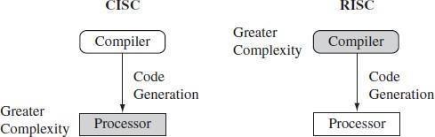
Fig: CISC vs. RISC
The RISC philosophy is implemented with four major design rules:
- Instructions—RISC processors have a reduced number of instruction classes. These classes provide simple operations that can each execute in a single cycle. The compiler or programmer synthesizes complicated operations (for example, a divide operation) by combining several simple instructions. Each instruction is having fixed length to allow the pipeline to fetch future instructions before decoding the current instruction.
- In contrast, in CISC processors the instructions are often of variable size and take many cycles to execute.
- Pipelines—The processing of instructions is broken down into smaller units that can be executed in parallel by pipelines. Ideally the pipeline advances by one step on each cycle for maximum throughput. Instructions can be decoded in one pipeline stage.
- There is no need for an instruction to be executed by a mini-program called microcode as on CISC processors.
- Registers—RISC machines have a large general-purpose register set. Any register can contain either data or an address. Registers act as the fast local memory store for all data processing operations.
- In contrast, CISC processors have dedicated registers for specific purposes.
- Load-store architecture—The processor operates on data held in registers. Separate load and store instructions transfer data between the register bank and external memory. Memory accesses are costly, so separating memory accesses from data processing provides an advantage because you can use data items held in the register bank multiple times without needing multiple memory accesses.
- In contrast, with a CISC design the data processing operations can act on memory directly.
- These design rules allow a RISC processor to be simpler, and thus the core can operate at higherclock frequencies.
o In contrast, traditional CISC processors are more complex and operate at lower clock frequencies.
THE ARM DESIGN PHYLOSOPHY:
There are a number of physical features that have driven the ARM processor design.
- Portable embedded systems require battery power. The ARM processor has been specially designed to be small to reduce power consumption and extend battery operation—essential for applications such as mobile phones and personal digital assistants (PDAs).
- High code density is another major requirement since embedded systems have limited memory due to cost and/or physical size restrictions—useful for applications that have limited on-board memory, such as mobile phones and mass storage devices.
- Embedded systems are price sensitive
- Hence, use slow and low-cost memory devices to get substantial savings— essential for high-volume applications like digital cameras.
- Also, reduce the area of the die taken up by the embedded processor; smaller the area used by the embedded processor, reduced cost of the design and manufacturing for the end product.
- ARM has incorporated hardware debug technology within the processor so that software engineers can view what is happening while the processor is executing code. With greater visibility, software engineers can resolve issues faster.
- The ARM core is not a pure RISC architecture because of the constraints of its primary application—the embedded system. In some sense, the strength of the ARM core is that it doesnot take the RISC concept too far.
Instruction Set for Embedded Systems:
The ARM instruction set differs from the pure RISC definition in several ways that make the ARM instruction set suitable for embedded applications:
- Variable cycle execution for certain instructions—Not every ARM instruction executes in a single cycle. For example, load-store-multiple instructions vary in the number of execution cycles depending upon the number of registers being transferred. The transfer can occur on sequential memory addresses. Code density is also improved since multiple register transfers are common operations at the start and end of functions.
- Inline barrel shifter leading to more complex instructions—The inline barrel shifter is a hardwarecomponent that preprocesses one of the input registers before it is used by an instruction. This expands the capability of many instructions to improve core performance and code density.
- Thumb 16-bit instruction set—ARM enhanced the processor core by adding a second 16-bit instruction set called Thumb that permits the ARM core to execute either 16- or 32-bit instructions. The 16-bit instructions improve code density by about 30% over 32-bit fixed-length instructions.
- Conditional execution—An instruction is only executed when a specific condition has been satisfied. This feature improves performance and code density by reducing branch instructions.
- Enhanced instructions—The enhanced digital signal processor (DSP) instructions were added to the standard ARM instruction set to support fast 16×16-bit multiplier operations. These instructions allow a faster-performing ARM processor.
These additional features have made the ARM processor one of the most commonly used 32-bit embedded processor cores.
EMBEDDED SYSTEM HARDWARE:
Embedded systems can control many different devices, from small sensors found on a production line, to the real-time control systems used on a NASA space probe. All these devices use a combination of software and hardware components.
The following Figure shows a typical embedded device based on an ARM core. Each box represents a feature or function. The lines connecting the boxes are the buses carrying data.
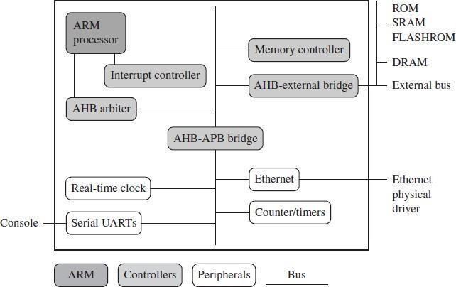
Figure: An ARM-based Embedded Device, a Microcontroller
We can separate the device into four main hardware components:
- The ARM processor controls the embedded device. Different versions of the ARM processor are available to suit the desired operating characteristics. An ARM processor comprises a core (the execution engine that processes instructions and manipulates data) plus the surrounding components (memory and cache) that interface it with a bus.
- Controllers coordinate important functional blocks of the system. Two commonly found controllers are interrupt and memory controllers.
- The peripherals provide all the input-output capability external to the chip and are responsible forthe uniqueness of the embedded device.
- A bus is used to communicate between different parts of the device.
ARM Bus Technology:
Embedded devices use an on-chip bus that is internal to the chip and that allows different peripheral devices to be interconnected with an ARM core.
There are two different classes of devices attached to the bus:
- The ARM processor core is a bus master—a logical device capable of initiating a data transferwith another device across the same bus.
- Peripherals tend to be bus slaves—logical devices capable only of responding to a transferrequest from a bus master device.
A bus has two architecture levels:
A physical level—covers the electrical characteristics and bus width (16, 32, or 64 bits).
The protocol—the logical rules that govern the communication between the processor and a peripheral.
AMBA Bus Protocol:
- The Advanced Microcontroller Bus Architecture (AMBA) was introduced in 1996 and has been widely adopted as the on-chip bus architecture used for ARM processors.
- The first AMBA buses introduced were the ARM System Bus (ASB) and the ARM Peripheral Bus (APB). Later ARM introduced another bus design, called the ARM High Performance Bus (AHB).
- Using AMBA, peripheral designers can reuse the same design on multiple projects. A peripheral can simply be bolted onto the on-chip bus without having to redesign an interface for each different processor architecture. This plug-and-play interface for hardware developers improves availability and time to market.
- AHB provides higher data throughput than ASB because it is based on a centralized multiplexed bus scheme rather than the ASB bidirectional bus design. This change allows the AHB bus to run at higher clock speeds.
- ARM has introduced two variations on the AHB bus: Multi-layer AHB and AHB-Lite.
- The Multi-layer AHB bus allows multiple active bus masters.
- AHB-Lite is a subset of the AHB bus and it is limited to a single bus master.
- The example device shown in the above Figure has three buses:
- an AHB bus for the high- performance peripherals
- an APB bus for the slower peripherals
- a third bus for external peripherals, proprietary to this device.
Memory:
An embedded system has to have some form of memory to store and execute code. You have to compare price, performance, and power consumption when deciding upon specific memory characteristics, such ashierarchy, width, and type.
Hierarchy: All computer systems have memory arranged in some form of hierarchy. The following Figure shows the memory trade-offs: the fastest memory cache is physically located nearer the ARM processor core and the slowest secondary memory is set further away. Generally the closer memory is to the processor core, the more it costs and the smaller its capacity.
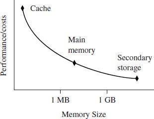
Figure: Memory Storage Trade-offs
- The cache is placed between main memory and the core. It is used to speed up data transfer between the processor and main memory. A cache provides an overall increase in performance but with a loss of predictable execution time. Although the cache increases the general performance of the system, it does not help real-time system response.
- The main memory is large—around 256 KB to 256 MB (or even greater), depending on the application—and is generally stored in separate chips. Load and store instructions access the main memory unless the values have been stored in the cache for fast access.
- Secondary storage is the largest and slowest form of memory. Hard disk drives and CD-ROMdrives are examples of secondary storage.
Width: The memory width is the number of bits the memory returns on each access—typically 8, 16, 32,or 64 bits.
- The memory width has a direct effect on the overall performance and cost ratio. Lower bit memories are less expensive, but reduce the system performance.
The following Table summarizes theoretical cycle times on an ARM processor using different memorywidth devices.
Table: Fetching Instruction from Memory
Instruction Size | 8-bit Memory | 16-bit Memory | 32-bit Memory |
ARM 32-bit | 4 cycles | 2 cycles | 1 cycles |
Thumb 16-bit | 2 cycles | 1 cycles | 1 cycles |
Types: There are many different types of memory:
- Read-only memory (ROM) is the least flexible of all memory types because it contains an image that is permanently set at production time and cannot be reprogrammed.
- ROMs are used in high-volume devices that require no updates or corrections.
Many devices also use a ROM to hold boot code.
- Flash ROM can be written to as well as read, but it is slow to write so you shouldn’t use it for holding dynamic data.
- Its main use is for holding the device firmware or storing long-term data that needs to be preserved after power is off. The erasing and writing of flash ROM are completely software controlled with no additional hardware circuitry required, which reduces the manufacturing costs.
- Dynamic random access memory (DRAM) is the most commonly used RAM for devices. It has the lowest cost per megabyte compared with other types of RAM. DRAM is dynamic—it needs to have its storage cells refreshed and given a new electronic charge every few milliseconds, so you need to set up a DRAM controller before using the memory.
- Static random access memory (SRAM) is faster than the more traditional DRAM, but requires more silicon area. SRAM is static—the RAM does not require refreshing. The access time for SRAM is considerably shorter than the equivalent DRAM because SRAM does not require a pause between data accesses. But cost of SRAM is high.
- Synchronous dynamic random access memory (SDRAM) is one of many subcategories of

DRAM. It can run at much higher clock speeds than conventional memory. SDRAM synchronizes itself with the processor bus, because it is clocked. Internally the data is fetched from memory cells, pipelined, and finally brought out on the bus in a burst.
Peripherals:
Embedded systems that interact with the outside world need some form of peripheral device. A peripheral device performs input and output functions for the chip by connecting to other devices or sensors that are off-chip.
- Each peripheral device usually performs a single function and may reside on-chip.
- Peripherals range from a simple serial communication device to a more complex
802.11 wireless device.
- All ARM peripherals are memory mapped—the programming interface is a set of memory- addressed registers. The address of these registers is an offset from a specific peripheral base address.
- Controllers are specialized peripherals that implement higher levels of functionality within an embedded system.
- Two important types of controllers are memory controllers and interrupt controllers.
Memory Controllers: Memory controllers connect different types of memory to the processor bus. o On power-up a memory controller is configured in hardware to allow certain memory
devices tobe active. These memory devices allow the initialization code to be executed.
Some memory devices must be set up by software; for example, when using DRAM, you first have to setup the memory timings and refresh rate before it can be accessed.
Interrupt Controllers: When a peripheral or device requires attention, it raises an interrupt to the processor. An interrupt controller provides a programmable governing policy that allows software to determine which peripheral or device can interrupt the processor at any specific time by setting the appropriate bits in the interrupt controller registers.
There are two types of interrupt controller available for the ARM processor: the standard interrupt controller and the vector interrupt controller.
- The standard interrupt controller sends an interrupt signal to the processor core when an externaldevice requests servicing. It can be programmed to ignore or mask an individual device or set of devices.
- The interrupt handler determines which device requires servicing by reading a device bitmap register in the interrupt controller.

page: 11
- The vector interrupt controller (VIC) is more powerful than the standard interrupt controller, because it prioritizes interrupts and simplifies the determination of which device caused the interrupt.
- Depending on the type, the VIC will either call the standard interrupt exception handler, which can load the address of the handler.
EMBEDDED SYSTEM SOFTWARE:
An embedded system needs software to drive it. The following Figure shows four typical software components required to control an embedded device.
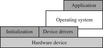
Figure: Software Abstraction Layers Executing on Hardware
- The initialization code is the first code executed on the board and is specific to a particular target or group of targets. It sets up the minimum parts of the board before handing control over to the operating system.
- The operating system provides an infrastructure to control applications and manage hardware system resources.
- The device drivers provide a consistent software interface to the peripherals on the hardware device.
- An application performs one of the tasks required for a device.
o For example, a mobile phone might have a diary application.
There may be multiple applications running on the same device, controlled by the operating
system.
o For example, the memory system normally requires reorganization of the memory map,as shown in the following Example.
Initialization (Boot) Code
Initialization code (or boot code)takes the processor from the reset state to a state where the operating system can run. It usually configures the memory controller and processor caches and initializes some devices. In a simple system the operating system might be replaced by a simple scheduler or debug monitor.
The initialization code handles a number of administrative tasks prior to handing control over to an operating system image. We can group these different tasks into three phases: initial hardware configuration, diagnostics, and booting.
Initial hardware configuration involves setting up the target platform so it can boot an image. Although the target platform itself comes up in a standard configuration, this configuration normally requires modification to satisfy the requirements of the booted image. For example, the memory system normally requires reorganization of the memory map, as shown in Example 1.1.
Diagnostics are often embedded in the initialization code. Diagnostic code tests the system by exercising the hardware target to check if the target is in working order. It also tracks down standard system-related issues. This type of testing is important for manufacturing since it occurs after the software product is complete. The primary purpose of diagnostic code is fault identification and isolation.
Booting involves loading an image and handing control over to that image. The boot process itself can be complicated if the system must boot different operating systems or different versions of the same operating system.
Booting an image is the final phase, but first you must load the image. Loading an image involves anything from copying an entire program including code and data into RAM, to just copying a data area containing volatile variables into RAM. Once booted, the system hands over control by modifying the program counter to point into the start of the image.
Sometimes, to reduce the image size, an image is compressed. The image is then decompressed either when it is loaded or when control is handed over to it
Example: Initializing or organizing memory is an important part of the initialization code, because many operating systems expect a known memory layout before they can start.
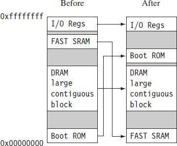
Figure: Memory Remapping
The above Figure shows memory before and after reorganization. It is common for ARM-based embedded systems to provide for memory remapping because it allows the system to start the initialization codefrom ROM at power-up. The initialization code then redefines or remaps the memory map to place RAM at address 0x00000000—an important step because then the exception vector table can be in RAM and thus can be reprogrammed.
Operating System:
- The initialization process prepares the hardware for an operating system to take control.
- OS controlling these resources, they can efficiently used by different applications running within the OS environment.
- ARM processors support over 50 operating systems. We can divide operating systems into two main categories: real-time operating systems (RTOSs) and platform operating systems.
- RTOSs provide guaranteed response times to events. Different operating systems have different amounts of control over the system response time.
- A hard real-time application requires a guaranteed response to work at all.
- In contrast, a soft real-time application requires a good response time, but the performance degrades more gracefully if the response time overruns.
- Platform operating systems require a memory management unit to manage large, non- real-timeapplications and tend to have secondary storage.
- The Linux operating system is a typical example of a platform operating system.
Applications:
- The operating system schedules applications—code dedicated to handle a particular task. An application implements a processing task; the operating system controls the environment.
- An embedded system can have one active application or several applications runningsimultaneously.
- ARM processors are found in numerous market segments, including networking, auto- motive,mobile and consumer devices, mass storage, and imaging.
- ARM processor is found in networking applications like home gateways, DSL modems for high-speed Internet communication, and 802.11 wireless communications.
- The mobile device segment is the largest application area for ARM processors, because
ARM PROCESSOR FUNDAMENTALS
A programmer can think of an ARM core as functional units connected by data buses, as shown in the following Figure.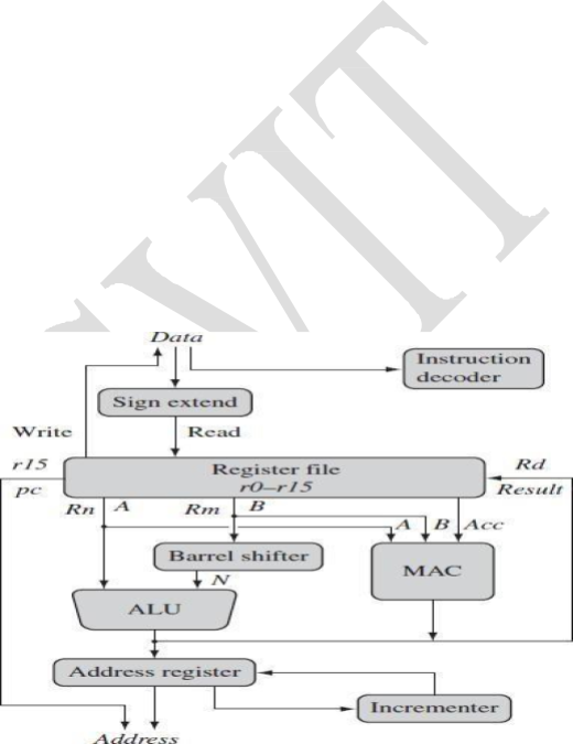
- Data enters the processor core through the Data bus. The data may be an instruction to execute or a data item.
- Figure shows a Von Neumann implementation of the ARM—data items and instructions share the same bus. (In contrast, Harvard implementations of the ARM use two different buses).
- The instruction decoder translates instructions before they are executed. Each instruction executed belongs to a particular instruction set.
The ARM processor, like all RISC processors, uses load-store architecture—means it has two instruction types for transferring data in and out of the processor:
Figure: ARM Core dataflow Model
The arrows represent the flow of data, the lines represent the buses, and the boxes represent either an operation unit or a storage area.
- load instructions copy data from memory to registers in the core
- store instructions copy data from registers to memory
- There are no data processing instructions that directly manipulate data in memory. Thus, data processing is carried out in registers.
- Data items are placed in the register file—a storage bank made up of 32-bit registers.
- Since the ARM core is a 32-bit processor, most instructions treat the registers as holding signed or unsigned 32-bit values. The sign extend hardware converts signed 8-bit and 16-bit numbers to 32-bit values as they are read from memory and placed in a register.
- ARM instructions typically have two source registers, Rn and Rm, and a single result or destination register, Rd. Source operands are read from the register file using the internal buses A and B, respectively.
- The ALU (arithmetic logic unit) or MAC (multiply-accumulate unit) takes the register values Rn and Rm from the A and B buses and computes a result. Data processing instructions write the result in Rd directly to the register file.
- Load and store instructions use the ALU to generate an address to be held in the address register and broadcast on the Address bus.
- One important feature of the ARM is that register Rm alternatively can be preprocessed in the barrel shifter before it enters the ALU. Together the barrel shifter and ALU can calculate a wide range of expressions and addresses.
- After passing through the functional units, the result in Rd is written back to the register file usingthe Result bus.
- For load and store instructions the Incrementer updates the address register before the core reads or writes the next register value from or to the next sequential memory location.
- The processor continues executing instructions until an exception or interrupt changes the normal execution flow.
REGISTERS:
General-purpose registers hold either data or an address. They are identified with the letter r prefixed to the register number. For example, register 4 is given the label r4. The Figure shows the active registers available in user mode. (A protected mode is normally used when executing applications).
- The processor can operate in seven different modes.
- All the registers shown are 32 bits in size.
- There are up to 18 active registers:
- 16 data registers and 2 processor status registers.
- The data registers visible to the programmer are r0 to r15.
- The ARM processor has three registers assigned to a particular task or special function: r13, r14,and r15. They are given with different labels to differentiate them from the other registers.
- Register r13 is traditionally used as the stack pointer (sp) and stores the head of the stack in the current processor mode.
- Register r14 is called the link register (lr) and is where the core puts the return addresswhenever it calls a subroutine.
- Register r15 is the program counter (pc) and contains the address of the next instructionto be fetched by the processor.
- In ARM state the registers r0 to r13 are orthogonal—any instruction that you can apply to r0 youcan equally well apply to any of the other registers.
- In addition to the 16 data registers, there are two program status registers: cpsr (current programstatus register) and spsr (saved program status register)
CURRENT PROGRAM STATUS REGISTER:
The ARM core uses the cpsr to monitor and control internal operations. The cpsr is a dedicated 32-bit register and resides in the register file. The following Figure shows the basic layout of a generic program status register. Note that the shaded parts are reserved for future expansion.
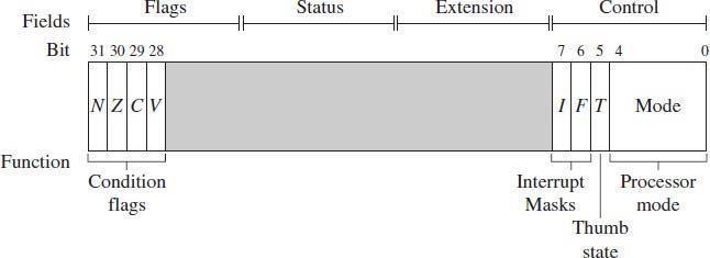
Figure: A Generic Program Status Register (psr)
The cpsr is divided into four fields, each 8 bits wide: flags, status, extension, and control. In current designs the extension and status fields are reserved for future use.
- The control field contains the processor mode, state, and interrupt mask bits.
- The flags field contains the condition flags.
Some ARM processor cores have extra bits allocated. For example, the J bit, which can be found in theflags field, is only available on Jazelle-enabled processors, which execute 8-bit instructions.
It is highly probable that future designs will assign extra bits for the monitoring and control of newfeatures.
Processor Modes:
- The processor mode determines which registers are active and the access rights to the cpsr
register itself. Each processor mode is either privileged or non-privileged:
- A privileged mode allows full read-write access to the cpsr.
- A non-privileged mode only allows read access to the control field in the cpsr, but still allows read-write access to the condition flags.
- There are seven processor modes in total:
- six privileged modes (abort, fast interrupt request, interrupt request, supervisor, system,and undefined)
- The processor enters abort mode when there is a failed attempt to access memory.
- Fast interrupt request and interrupt request modes correspond to the two interrupt levels available on the ARM processor.
- Supervisor mode is the mode that the processor is in after reset and is generally the mode that an operating system kernel operates in.
- System mode is a special version of user mode that allows full read-write
accessto the cpsr.
- Undefined mode is used when the processor encounters an instruction that is undefined or not supported by the implementation.
- one non-privileged mode (user).
User mode is used for programs and applications.
Banked Registers:
The following Figure shows all 37 registers in the register file.
- Of these, 20 registers are hidden from a program at different times.
- These registers are called banked registers and are identified by the shading in the diagram.
- They are available only when the processor is in a particular mode; for example, abort mode has banked registers r13_abt, r14_abt and spsr_abt.
- Banked registers of a particular mode are denoted by an underline character post- fixed to the mode mnemonic or _mode.
- Every processor mode except user mode can change mode by writing directly to the mode bits of the cpsr.
- All processor modes except system mode have a set of associated banked registers that are a subset of the main 16 registers.
- A banked register maps one-to-one onto a user mode register.
- If you change processor mode, a banked register from the new mode will replace an existing register.
- For example, when the processor is in the interrupt request mode, the instructions you execute still access registers named r13 and r14. However, these registers are the banked registers r13_irq and r14_irq. The user mode registers r13_usr and r14_usr are not affected by the instruction referencing these registers. A program still has normal access to the other registers r0 to r12.
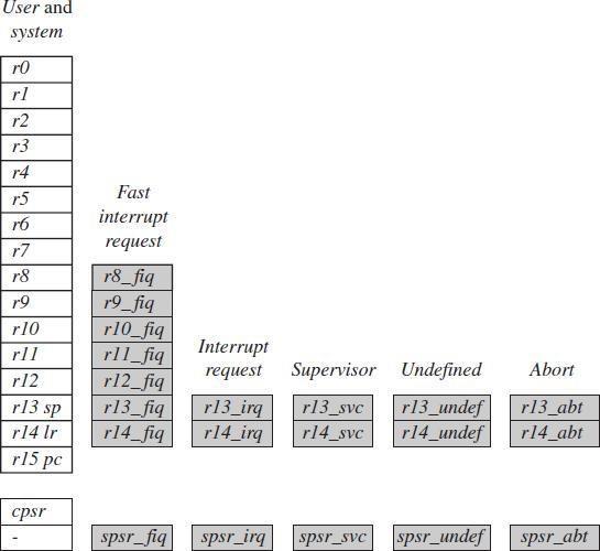
Figure: Complete ARM Register Set
- The processor mode can be changed by a program that writes directly to the cpsr (the processor core has to be in privileged mode) or by hardware when the core responds to an exception or interrupt.
- The following exceptions and interrupts cause a mode change: reset, interrupt request, fast interrupt request, software interrupt, data abort, prefetch abort, and undefined instruction.
- Exceptions and interrupts suspend the normal execution of sequential instructions and jump to a specific location.
Comparision between ARM and Thumb Instruction:
- | ARM (cspr T = 0) | Thumb (cspr T = 1) |
Instruction size | 32-bit | 16-bit |
Core instructions | 58 | 30 |
Conditional execution | most | only branch instructions |
Data processing instructions | access to barrel shifter and ALU | separate barrel shifter and ALU instructions |
Program status register | read-write in privileged mode | no direct access |
Register usage | 15 general-purpose registers +pc | 8 general-purpose registers +7 high registers +pc |
Condition Flags:

the S instruction suffix.
o For example, if a SUBS subtract instruction results in a register value of zero, then the Z
Flag in the cpsr is set. This particular subtract instruction specifically updates the cpsr.
- With processor cores that include the DSP extensions, the Q bit indicates if an overflow or saturation has occurred in an enhanced DSP instruction. The flag is “sticky” in the sense that the hardware only sets this flag. To clear the flag you need to write to the cpsr directly.
- In Jazelle-enabled processors, the J bit reflects the state of the core; if it is set, the core is in Jazelle state. The J bit is not generally usable and is only available on some processor cores. To take advantage of Jazelle, extra software has to be licensed from both ARM Limited and Sun Microsystems.
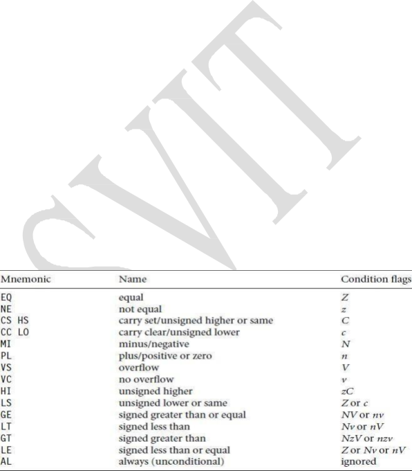
- Most ARM instructions can be executed conditionally on the value of the condition flags. The following Table lists the condition flags and a short description on what causes them to be set.
Table: Condition Flags
Flag | Flag Name | Set When |
Q | Saturation | the result causes an overflow and/or saturation |
V | OVerflow | the result causes a signed overflow |
C | Carry | the result causes an unsigned carry |
Z | Zero | the result is zero |
N | Negative | bit 31 of the result is a binary 1 |
These flags are located in the most significant bits in the cpsr. These bits are used for conditional execution. The following Figure shows a typical value for the cpsr with both DSP extensions and Jazelle.
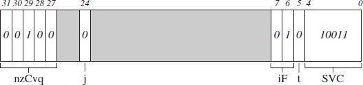
- For the condition flags a capital letter shows that the flag has been set. For interrupts a capital letter shows that an interrupt is disabled.
- In the cpsr example shown in above Figure, the C flag is the only condition flag set. The rest nzvq flags are all clear.
- The processor is in ARM state because neither the Jazelle j nor Thumb t bits are set. The IRQ interrupts are enabled, and FIQ interrupts are disabled.
- Finally, you can see from the Figure, the processor is in supervisor (SVC) mode, since the mode[4:0] is equal to binary 10011.
Conditional Execution:
- Conditional execution controls whether or not the core will execute an instruction.
- Prior to execution, the processor compares the condition attribute with the condition flags in the cpsr. If they match, then the instruction is executed; otherwise the instruction is ignored.
- The condition attribute is post-fixed to the instruction mnemonic, which is encoded into the instruction.
- The following Table lists the conditional execution code mnemonics. When a condition mnemonic is not present, the default behavior is to set it to always (AL) execute.
Table: Condition Mnemonics
PIPELINE:
- A pipeline is the mechanism in a RISC processor, which is used to execute instructions.
- Pipeline speeds up execution by fetching the next instruction while other instructions are being decoded and executed.

Figure: ARM7 Three-stage Pipeline
The above Figure shows a three-stage pipeline:
- Fetch loads an instruction from memory.
- Decode identifies the instruction to be executed.
- Execute processes the instruction and writes the result back to a register.
- The below Figure shows a sequence of three instructions being fetched, decoded, and executed by the processor.
- The three instructions are placed into the pipeline sequentially.
- In the first cycle, the core fetches the ADD instruction from memory.
- In the second cycle, the core fetches the SUB instruction and decodes the ADD instruction.In the third cycle, both the SUB and ADD instructions are moved along the pipeline. The ADD instruction is executed, the SUB instruction is decoded, and the CMP instruction is fetched.This procedure is called filling the pipeline.
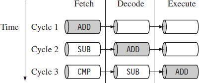
Below Figure shows Pipelined instruction sequence.
- The pipeline allows the core to execute an instruction every cycle.
- As the pipeline length increases, the amount of work done at each stage is reduced, which allows the processor to attain a higher operating frequency. This in turn increases the performance.
- The increased pipeline length also means increased system latency and there can be data dependency between certain stages.
EXCEPTIONS, INTERRUPTS AND THE VECTOR TABLE:
- When an exception or interrupt occurs, the processor sets the pc to a specific memory address.The address is within a special address range called the vector table.
- The entries in the vector table are instructions that branch to specific routines designed to handle a particular exception or interrupt.
- The memory map address 0x00000000 (or in some processors starting at the offset 0xffff0000) is reserved for the vector table, a set of 32-bit words.
- When an exception or interrupt occurs, the processor suspends normal execution and starts loading instructions from the exception vector table (see the following Table).
Table: The Vector Table
Exception/Interrupt | Shorth and | Address | High Address |
Reset | RESET | 0x00000000 | 0x00000000 |
Undefined instruction | UNDEF | 0x00000004 | 0xffff0004 |
Software interrupt | SWI | 0x00000008 | 0xffff0008 |
Prefetch abort | PABT | 0x0000000c | 0xffff000c |
Data abort | SABT | 0x00000010 | 0xffff0010 |
Reserved | – | 0x00000014 | 0xffff0014 |
Interrupt request | IRQ | 0x00000018 | 0xffff0018 |
Fast interrupt request | FIQ | 0x0000001c | 0xffff001c |
- Each vector table entry contains a form of branch instruction pointing to the start of a specific routine:
- Reset vector is the location of the first instruction executed by the processor when power is applied. This instruction branches to the initialization code.
- Undefined instruction vector is used when the processor cannot decode an instruction.
- Software interrupt vector is called when you execute a SWI instruction. The SWI instruction is frequently used as the mechanism to invoke an operating system routine.
- Prefetch abort vector occurs when the processor attempts to fetch an instruction from an address without the correct access permissions. The actual abort occurs in the decode stage.
- Data abort vector is similar to a prefetch abort, but is raised when an instruction attemptsto access data memory without the correct access permissions.
- Interrupt request vector is used by external hardware to interrupt the normal execution flow of the processor. It can only be raised if IRQs are not masked in the cpsr.
- Fast interrupt request vector is similar to the interrupt request, but is reserved for hardware requiring faster response times. It can only be raised if FIQs are not masked in the cpsr.
CORE EXTENSIONS:
- Core extensions are the standard hardware components placed next to the ARM core.
- They improve performance, manage resources, and provide extra functionality and are designedto provide flexibility in handling particular applications.
Each ARM family has different extensions available. There are three hardware extensions: cache andtightly coupled memory, memory management, and the coprocessor interface.
Cache and Tightly Coupled Memory:
- The cache is a block of fast memory placed between main memory and the core. It allows for more efficient fetches from some memory types. With a cache the processor core can run for the majority of the time without having to wait for data from slow external memory.
- Most ARM-based embedded systems use a single-level cache internal to the processor.
- ARM has two forms of cache. The first is found attached to the Von Neumann–style cores. It combines both data and instruction into a single unified cache, as shown in the following Figure.
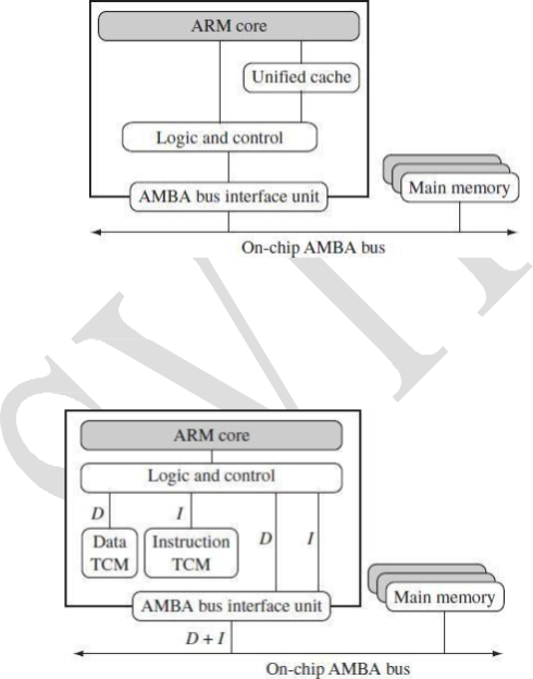
Figure: Von Neumann Architecture with Cache
- The second form, attached to the Harvard-style cores, has separate caches for data and instruction, as shown in the following Figure.
Figure: Harvard Architecture with TCMs
- A cache provides an overall increase in performance, but at the expense of predictable execution. But the real-time systems require the code execution to be deterministic— the time taken for loading and storing instructions or data must be predictable.
- This is achieved using a form of memory called tightly coupled memory (TCM). TCM is fast SRAM located close to the core and guarantees the clock cycles required to fetch instructions or data.
- TCMs appear as memory in the address map and can be accessed as fast memory.
Memory Management:
- Embedded systems often use multiple memory devices. It is usually necessary to have a method to organize these devices and protect the system from applications trying to make inappropriate accesses to hardware. This is achieved with the assistance of memory management hardware.
- ARM cores have three different types of memory management hardware—
- no extensions providing no protection
- a memory protection unit (MPU) providing limited protection
- a memory management unit (MMU) providing full protection.
- Non protected memory is fixed and provides very little flexibility. It is normally used for small, simple embedded systems that require no protection from rogue applications.
- MPUs employ a simple system that uses a limited number of memory regions. These regions are controlled with a set of special coprocessor registers, and each region is defined with specific access permissions. This type of memory management is used for systems that require memory protection but don’t have a complex memory map.
- MMUs are the most comprehensive memory management hardware available on the ARM. The MMU uses a set of translation tables to provide fine-grained control over memory. These tables are stored in main memory and provide a virtual-to-physical address map as well as access permissions. MMUs are designed for more sophisticated platform operating systems that support multitasking.
Coprocessors:
- Coprocessors can be attached to the ARM processor. A coprocessor extends the processing features of a core by extending the instruction set or by providing configuration registers. More than one coprocessor can be added to the ARM core via the coprocessor interface.
- The coprocessor can be accessed through a group of dedicated ARM instructions that provide a load-store type interface.
- For example, coprocessor 15: The ARM processor uses coprocessor 15 registers to control the cache, TCMs, and memory management.
- The coprocessor can also extend the instruction set by providing a specialized group of new instructions.
- For example, there are a set of specialized instructions that can be added to the standard ARM instruction set to process vector floating-point (VFP) operations.
- These new instructions are processed in the decode stage of the ARM pipeline.
- If the decode stage sees a coprocessor instruction, then it offers it to the relevant coprocessor.
- If the coprocessor is not present or doesn’t recognize the instruction, then the ARM takes an undefined instruction exception, which allows you to emulate the behavior of the coprocessor in software.

Previous year questions
- With neat block diagram, explain the ARM based Embedded device Microcontroller.
6M(Aug 21)
- With neat diagram outline the various functional block of embedded system.6M
- Explain RISC design principle. 4M(Feb21)
- Differentiate between CISC and RISC processors 4M(sept2020)
- Explain the Instruction set for Embedded systems. 6M
- Explain the Embedded system hardware. 6M(sept2020)
- Explain ARM core data flow model with neat diagram. 6M(Aug ,Feb21)8M(sept2020)(JAN2020)8M (2018)
- Explain Process Modes of CPSR with respect to ARM Processors. 6M (Aug 21)7M
- Explain the Pipeline mechanism in ARM Processors. 8M(Aug2021), 4M(Feb2021),6M(sept 2020)
- Explain interrupt handling in ARM processor. 4M(Feb21)
- Explain the memory remapping of embedded system software for initialization(Boot)code. 6M
- Explain ARM processors execution modes along with complete register set. 8M
- With neat diagram illustrate the seven processor modes. 8M
- Explain registers used under different processor modes. 5M



