MODULE 1
What is Embedded System?
An Electronic/Electro mechanical system which is designed to perform a specific function and is a combination of both hardware and firmware (Software)
E.g. Electronic Toys, Mobile Handsets, Washing Machines, Air Conditioners, Automotive Control Units, Set Top Box, DVD Player etc…
Embedded Systems are
→ Unique in character and behavior
→ With specialized hardware and software
Embedded Systems Vs General Computing Systems
General Purpose Computing System | Embedded System |
A system which is a combination of generic hardware and General-Purpose Operating System for executing a variety of applications | A system which is a combination of special purpose hardware and embedded OS for executing a specific set of applications |
Contain a General-Purpose Operating System (GPOS) | May or may not contain an operating system for functioning |
Applications are alterable (programmable) by user (It is possible for the end user to re install the Operating System, and add or remove user applications) | The firmware of the embedded system is pre- programmed and it is non-alterable by end- user |
Performance is the key deciding factor on the selection of the system. Always “Faster is Better‟ | Application specific requirements (like performance, power requirements, memory usage etc) are the key deciding factors |
Less/not at all tailored towards reduced operating power requirements, options for different levels of power management. | Highly tailored to take advantage of the power saving modes supported by hardware and Operating System |
Response requirements are not time critical | For certain category of embedded systems like mission critical systems, the response time requirement is highly critical |
Need not be deterministic in execution behavior | Execution behavior is deterministic for certain type of embedded systems like “Hard Real Time‟ systems |
History of Embedded Systems
- First Recognized Modern Embedded System: Apollo Guidance Computer (AGC) developed by Charles Stark Draper at the MIT Instrumentation Laboratory.
→ Command module (CM)
→ Lunar Excursion module (LEM)
- RAM size 256, 1K ,2K words
- ROM size 4K,10K,36K words
- Clock frequency is 1.024MH
- 5000 ,3-input RTL NOR gates are used
- User interface is DSKY (display/Keyboard)
- First Mass Produced Embedded System: Autonetics D-17 Guidance computer for Minuteman-I missile
Classification of Embedded Systems
- Based on Generation
- Based on Complexity & Performance Requirements
- Based on deterministic behavior
- Based on Triggering
Embedded Systems - Classification based on Generation
First Generation: The early embedded systems built around 8-bit microprocessors like 8085 and Z80 and 4-bit microcontrollers Example are, stepper motor control units, Digital Telephone Keypads etc.
Second Generation: Embedded Systems built around 16-bit microprocessors and 8 or 16-bit microcontrollers, following the first-generation embedded systems. Example are, SCADA, Data Acquisition Systems etc.
Third Generation: Embedded Systems built around high performance 16/32-bit Microprocessors/controllers, Application Specific Instruction set processors like Digital Signal Processors (DSPs), and Application Specific Integrated Circuits (ASICs). The instruction set is complex and powerful. Example are, Robotics, industrial process control, networking etc. Fourth Generation: Embedded Systems built around System on Chips (SoC’s), Re- configurable processors and multicore processors. It brings high performance, tight integration
and miniaturization into the embedded device market. Example are, Smart phone devices, MIDs etc.
Embedded Systems - Classification based on Complexity & Performance
Small Scale: The embedded systems built around low performance and low cost 8- or 16-bit microprocessors/ microcontrollers. It is suitable for simple applications and where performance is not time critical. It may or may not contain OS.
Medium Scale: Embedded Systems built around medium performance, low cost 16- or 32-bit microprocessors / microcontrollers or DSPs. These are slightly complex in hardware and firmware. It may contain GPOS/RTOS.
Large Scale/Complex: Embedded Systems built around high performance 32- or 64-bit RISC processors/controllers, RSoC or multi-core processors and PLD. It requires complex hardware and software. These systems may contain multiple processors/controllers and co- units/hardware accelerators for offloading the processing requirements from the main processor. It contains RTOS for scheduling, prioritization and management.
Embedded Systems - Classification Based on deterministic behavior
It is applicable for Real Time systems. The application/task execution behavior for an embedded system can be either deterministic or non-deterministic
Soft Real time Systems: Missing a deadline may not be critical and can be tolerated to a certain degree
Hard Real time systems: Missing a program/task execution time deadline can have catastrophic consequences (financial, human loss of life, etc.)
Embedded Systems - Classification Based on Triggering
These are classified into two types
Event Triggered: Activities within the system (e.g., task run-times) are dynamic and depend upon occurrence of different events.
Time triggered: Activities within the system follow a statically computed schedule (i.e., they are allocated time slots during which they can take place) and thus by nature are predictable
Major Application Areas of Embedded Systems
- Consumer Electronics: Camcorders, Cameras etc.
- Household Appliances: Television, DVD players, washing machine, Fridge, Microwave Oven etc.
- Home Automation and Security Systems: Air conditioners, sprinklers, Intruder detection alarms, Closed Circuit Television Cameras, Fire alarms etc.
- Automotive Industry: Anti-lock breaking systems (ABS), Engine Control, Ignition Systems, Automatic Navigation Systems etc.
- Telecom: Cellular Telephones, Telephone switches, Handset Multimedia Applications etc.
- Computer Peripherals: Printers, Scanners, Fax machines etc.
- Computer Networking Systems: Network Routers, Switches, Hubs, Firewalls etc.
- Health Care: Different Kinds of Scanners, EEG, ECG Machines etc.
- Measurement & Instrumentation: Digital multi meters, Digital CROs, Logic Analyzers PLC systems etc.
- Banking & Retail: Automatic Teller Machines (ATM) and Currency counters, Point of Sales (POS)
- Card Readers: Barcode, Smart Card Readers, Hand held Devices etc.
Purpose of Embedded Systems
Each Embedded Systems is designed to serve the purpose of any one or a combination of the following tasks.
- Data Collection/Storage/Representation
- Data Communication
- Data (Signal) Processing
- Monitoring
- Control
- Application Specific User Interface
Data Collection/Storage/Representation
→ Performs acquisition of data from the external world.
→ The collected data can be either analog or digital
→ Data collection is usually done for storage, analysis, manipulation and transmission
→ The collected data may be stored directly in the system or may be transmitted to some other systems or it may be processed by the system or it may be deleted instantly after giving a meaningful representation
- Data Communication
→ Embedded Data communication systems are deployed in applications ranging from complex satellite communication systems to simple home networking systems
→ Embedded Data communication systems are dedicated for data communication
→ The data communication can happen through a wired interface (like Ethernet, RS- 232C/USB/IEEE1394 etc) or wireless interface (like Wi-Fi, GSM,/GPRS, Bluetooth, ZigBee etc)
→ Network hubs, Routers, switches, Modems etc are typical examples for dedicated data transmission embedded systems
- Data (Signal) Processing
→ Embedded systems with Signal processing functionalities are employed in applications demanding signal processing like Speech coding, synthesis, audio video codec, transmission applications etc
→ Computational intensive systems
→ Employs Digital Signal Processors (DSPs)
Monitoring
→ Embedded systems coming under this category are specifically designed for monitoring purpose
→ They are used for determining the state of some variables using input sensors
→ They cannot impose control over variables.
→ Electro Cardiogram (ECG) machine for monitoring the heart beat of a patient is a typical example for this
→ The sensors used in ECG are the different Electrodes connected to the patient’s body
→ Measuring instruments like Digital CRO, Digital Multi meter, Logic Analyzer etc used in Control & Instrumentation applications are also examples of embedded systems for monitoring purpose
Control
→ Embedded systems with control functionalities are used for imposing control over some variables according to the changes in input variables
→ Embedded system with control functionality contains both sensors and actuators
→ Sensors are connected to the input port for capturing the changes in environmental variable or measuring variable
→ The actuators connected to the output port are controlled according to the changes in input variable to put an impact on the controlling variable to bring the controlled variable to the specified range
→ Air conditioner for controlling room temperature is a typical example for embedded system with Control functionality
→ Air conditioner contains a room temperature sensing element (sensor) which may be a thermistor and a handheld unit for setting up (feeding) the desired temperature
→ The air compressor unit acts as the actuator. The compressor is controlled according to the current room temperature and the desired temperature set by the end user.
Application Specific User Interface
→ Embedded systems which are designed for a specific application
→ Contains Application Specific User interface (rather than general standard UI) like key board, Display units etc
→ Aimed at a specific target group of users
→ Mobile handsets, Control units in industrial applications etc are examples
The Core of the Embedded Systems
The core of the embedded system falls into any one of the following categories.
- General Purpose and Domain Specific Processors
→ Microprocessors
→ Microcontrollers
→ Digital Signal Processors
- Programmable Logic Devices (PLDs)
- Application Specific Integrated Circuits (ASICs)
- Commercial off the shelf Components (COTS)
General Purpose and Domain Specific Processor
- Almost 80% of the embedded systems are processor/ controller based.
- The processor may be microprocessor or a microcontroller or digital signal processor, depending on the domain and application.
Microprocessor
- A silicon chip representing a Central Processing Unit (CPU), which is capable of performing arithmetic as well as logical operations according to a pre-defined set of Instructions, which is specific to the manufacturer
- In general, the CPU contains the Arithmetic and Logic Unit (ALU), Control Unit and Working registers
- Microprocessor is a dependant unit and it requires the combination of other hardware like Memory, Timer Unit, and Interrupt Controller etc for proper functioning.
- Intel claims the credit for developing the first Microprocessor unit Intel 4004, a 4 bit processor which was released in Nov 1971
- Developers of microprocessors.
Intel – Intel 4004 – November 1971(4-bit) Intel – Intel 4040.
Intel – Intel 8008 – April 1972.
Intel – Intel 8080 – April 1974(8-bit). Motorola – Motorola 6800.
Intel – Intel 8085 – 1976. Zilog - Z80 – July 1976
Microcontroller:
- A highly integrated silicon chip containing a CPU, scratch pad RAM, Special and General- purpose Register Arrays, On Chip ROM/FLASH memory for program storage, Timer and Interrupt control units and dedicated I/O ports
- Microcontrollers can be considered as a super set of Microprocessors
- Microcontroller can be general purpose (like Intel 8051, designed for generic applications and domains) or application specific (Like Automotive AVR from Atmel Corporation. Designed specifically for automotive applications)
- Since a microcontroller contains all the necessary functional blocks for independent working, they found greater place in the embedded domain in place of microprocessors
- Microcontrollers are cheap, cost effective and are readily available in the market
- Texas Instruments TMS 1000 is considered as the world‟s first microcontroller
Microprocessor Vs Microcontroller
Microprocessor | Microcontroller |
A silicon chip representing a Central Processing Unit (CPU), which is capable of performing arithmetic as well as logical operations according to a pre-defined set of Instructions | A microcontroller is a highly integrated chip that contains a CPU, scratch pad RAM, Special and General-purpose Register Arrays, On Chip ROM/FLASH memory for program storage, Timer and Interrupt control units and dedicated I/O ports |
It is a dependent unit. It requires the combination of other chips like Timers, Program and data memory chips, Interrupt controllers etc. for functioning | It is a self-contained unit and it doesn’t require external Interrupt Controller, Timer, UART etc. for its functioning |
Most of the time general purpose in design and operation | Mostly application oriented or domain specific |
Doesn’t contains a built in I/O port. The I/O Port functionality needs to be implemented with the help of external Programmable Peripheral Interface Chips like 8255 | Most of the processors contain multiple built-in I/O ports which can be operated as a single 8 or 16- or 32-bit Port or as individual port pins |
Targeted for high end market where performance is important | Targeted for embedded market where performance is not so critical (At present this demarcation is invalid) |
Limited power saving options compared to microcontrollers | Includes lot of power saving features |
General Purpose Processor (GPP) Vs Application Specific Instruction Set Processor (ASIP)
- General Purpose Processor or GPP is a processor designed for general computational tasks
- GPPs are produced in large volumes and targeting the general market. Due to the high- volume production, the per unit cost for a chip is low compared to ASIC or other specific ICs
- A typical general-purpose processor contains an Arithmetic and Logic Unit (ALU) and Control Unit (CU)
- Application Specific Instruction Set processors (ASIPs) are processors with architecture and instruction set optimized to specific domain/application requirements like Network processing, Automotive, Telecom, media applications, digital signal processing, control applications etc.
- ASIPs fill the architectural spectrum between General Purpose Processors and Application Specific Integrated Circuits (ASICs)
- The need for an ASIP arises when the traditional general purpose processor are unable to meet the increasing application needs
- Some Microcontrollers (like Automotive AVR, USB AVR from Atmel), System on Chips, Digital Signal Processors etc are examples of Application Specific Instruction Set Processors (ASIPs)
- ASIPs incorporate a processor and on-chip peripherals, demanded by the application requirement, program and data memory
Digital Signal Processors (DSPs)
- Powerful special purpose 8/16/32 bit microprocessors designed specifically to meet the computational demands and power constraints of today's embedded audio, video, and communications applications
- Digital Signal Processors are 2 to 3 times faster than the general-purpose microprocessors in signal processing applications
- DSPs implement algorithms in hardware which speeds up the execution whereas general purpose processors implement the algorithm in firmware and the speed of execution depends primarily on the clock for the processors
- DSP can be viewed as a microchip designed for performing high speed computational operations for addition, subtraction, multiplication and division
- A typical Digital Signal Processor incorporates the following key units
→ Program Memory: It is a memory for storing the program required by DSP to process the data.
→ Data Memory: It is a working memory for storing temporary variables and data/signal to be processed.
→ Computational Engine: It performs the signal processing in accordance with the stored program memory computational engine incorporated many specialized arithmetic units and each of them operates simultaneously to increase the execution speed. It also includes multiple hardware shifters for shifting operands and saves execution time.
→ I/O Unit: It acts as an interface between the outside world and DSP. It is responsible for capturing signals
- Audio video signal processing, telecommunication and multimedia applications are typical examples where DSP is employed
RISC V/s CISC Processors/Controllers
RISC | CISC |
Lesser no. of instructions | Greater no. of Instructions |
Instruction Pipelining and increased execution speed | Generally, no instruction pipelining feature |
Orthogonal Instruction Set (Allows each instruction to operate on any register and use any addressing mode) | Non-Orthogonal Instruction Set (All instructions are not allowed to operate on any register and use any addressing mode. It is instruction specific) |
Operations are performed on registers only; the only memory operations are load and store | Operations are performed on registers or memory depending on the instruction |
Large number of registers are available | Limited no. of general-purpose registers |
Programmer needs to write more code to execute a task since the instructions are simpler ones | A programmer can achieve the desired functionality with a single instruction which in turn provides the effect of using more simpler single instructions in RISC |
Single, Fixed length Instructions | Variable length Instructions |
Less Silicon usage and pin count | More silicon usage since more additional decoder logic is required to implement the complex instruction decoding. |
With Harvard Architecture | Can be Harvard or Von-Neumann Architecture |
Harvard V/s Von-Neumann Processor/Controller Architecture
- The terms Harvard and Von-Neumann refers to the processor architecture design.
- Microprocessors/controllers based on the Von-Neumann architecture shares a single common bus for fetching both instructions and data. Program instructions and data are stored in a common main memory
- Microprocessors/controllers based on the Harvard architecture will have separate data bus and instruction bus. This allows the data transfer and program fetching to occur simultaneously on both buses
- With Harvard architecture, the data memory can be read and written while the program memory is being accessed. These separated data memory and code memory buses allow one instruction to execute while the next instruction is fetched (“Pre-fetching”)
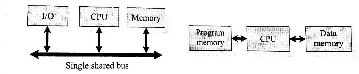
Harvard Architecture | Von-Neumann Architecture |
Separate buses for Instruction and Data fetching | Single shared bus for Instruction and Data fetching |
Easier to Pipeline, so high performance can be achieved | Low performance Compared to Harvard Architecture |
Comparatively high cost | Cheaper |
No memory alignment problems | Allows self modifying codes |
Since data memory and program memory are stored physically in different locations, no chances for accidental corruption of program memory | Since data memory and program memory are stored physically in same chip, chances for accidental corruption of program memory |
Big-endian V/s Little-endian processors:
- Endianness specifies the order in which the data is stored in the memory by processor operations in a multi byte system (Processors whose word size is greater than one byte). Suppose the word length is two byte then data can be stored in memory in two different ways
→ Higher order of data byte at the higher memory and lower order of data byte at location just below the higher memory
→ Lower order of data byte at the higher memory and higher order of data byte at location just below the higher memory
- Little-endian means the lower-order byte of the data is stored in memory at the lowest address, and the higher-order byte at the highest address. (The little end comes first)
- Big-endian means the higher-order byte of the data is stored in memory at the lowest address, and the lower-order byte at the highest address. (The big end comes first.)
Load Store Operation & Instruction Pipelining
The RISC processor instruction set is orthogonal and it operates on registers. The memory access related operations are performed by the special instructions load and store. If the operand is specified as memory location, the content of it is loaded to a register using the load instruction. The instruction store stores data from a specified register to a specified memory location
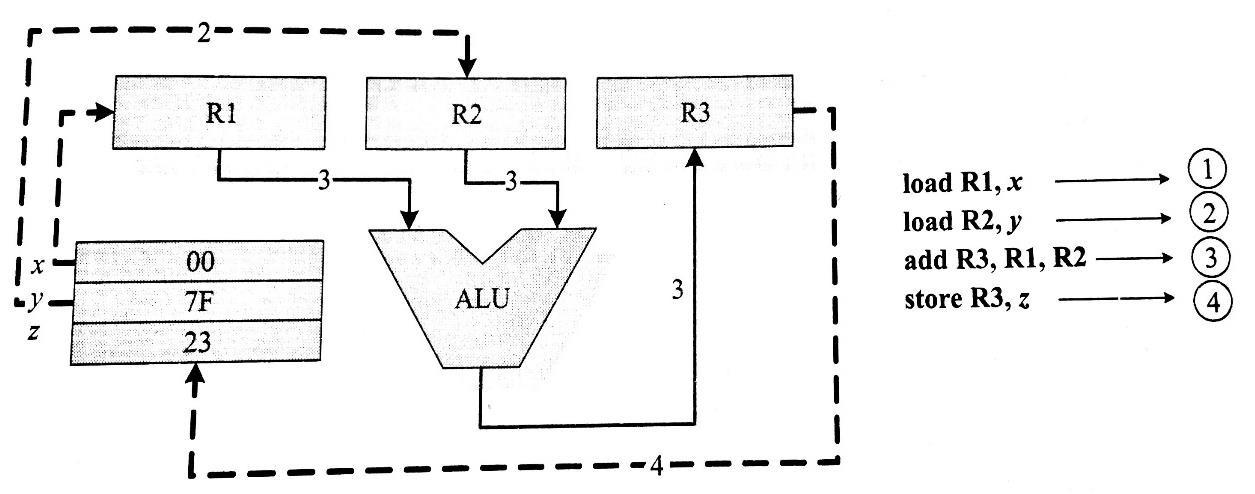
- The conventional instruction execution by the processor follows the fetch-decode-execute sequence
- The fetch part fetches the instruction from program memory or code memory and the decode part decodes the instruction to generate the necessary control signals
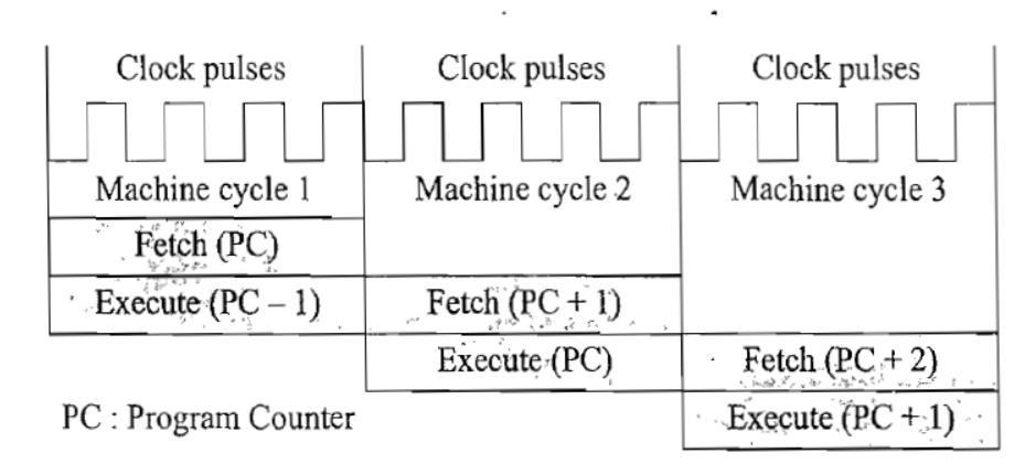
- The execute stage reads the operands, perform ALU operations and stores the result. In conventional program execution, the fetch and decode operations are performed in sequence
- During the decode operation the memory address bus is available and if it possible to effectively utilize it for an instruction fetch, the processing speed can be increased
- In its simplest form instruction pipelining refers to the overlapped execution of instructions
Application Specific Integrated Circuit (ASIC)
- A microchip designed to perform a specific or unique application. It is used as replacement to conventional general-purpose logic chips.
- ASIC integrates several functions into a single chip and thereby reduces the system development cost
- Most of the ASICs are proprietary products. As a single chip, ASIC consumes very small area in the total system and thereby helps in the design of smaller systems with high capabilities/functionalities.
- ASICs can be pre-fabricated for a special application or it can be custom fabricated by using the components from a re-usable “building block‟ library of components for a particular customer application
- Fabrication of ASICs requires a non-refundable initial investment (Non-Recurring Engineering (NRE) charges) for the process technology and configuration expenses
- If the Non-Recurring Engineering Charges (NRE) is born by a third party and the Application Specific Integrated Circuit (ASIC) is made openly available in the market, the ASIC is referred as Application Specific Standard Product (ASSP)
- The ASSP is marketed to multiple customers just as a general-purpose product, but to a smaller number of customers since it is for a specific application.
- Some ASICs are proprietary products, the developers are not interested in revealing the internal details.
Programmable Logic Devices (PLDs):
- Logic devices provide specific functions, including device-to-device interfacing, data communication, signal processing, data display, timing and control operations, and almost every other function a system must perform.
- Logic devices can be classified into two broad categories - Fixed and Programmable. The circuits in a fixed logic device are permanent, they perform one function or set of functions
- once manufactured, they cannot be changed
- Programmable logic devices (PLDs) offer customers a wide range of logic capacity, features, speed, and voltage characteristics - and these devices can be re-configured to perform any number of functions at any time
- Designers can use inexpensive software tools to quickly develop, simulate, and test their logic designs in PLD based design. The design can be quickly programmed into a device, and immediately tested in a live circuit
- PLDs are based on re-writable memory technology and the device is reprogrammed to change the design
Programmable Logic Devices (PLDs) – CPLDs and FPGA
Field Programmable Gate Arrays (FPGAs) and Complex Programmable Logic Devices (CPLDs) are the two major types of programmable logic devices
FPGA:
- FPGA is an IC designed to be configured by a designer after manufacturing.
- FPGAs offer the highest amount of logic density, the most features, and the highest performance.
- Logic gate is Medium to high density ranging from 1K to 500K system gates
- These advanced FPGA devices also offer features such as built-in hardwired processors (such as the IBM Power PC), substantial amounts of memory, clock management systems, and support for many of the latest, very fast device-to-device signaling technologies
- These advanced FPGA devices also offer features such as built-in hardwired processors, substantial amounts of memory, clock management systems, and support for many of the latest, very fast device-to-device signaling technologies.
- FPGAs are used in a wide variety of applications ranging from data processing and storage, to instrumentation, telecommunications, and digital signal processing
CPLD:
- A complex programmable logic device (CPLD) is a programmable logic device with complexity between that of PALs and FPGAs, and architectural features of both.
- CPLDs, by contrast, offer much smaller amounts of logic - up to about 10,000 gates.
- CPLDs offer very predictable timing characteristics and are therefore ideal for critical control applications.
- CPLDs such as the Xilinx Cool Runner series also require extremely low amounts of power and are very inexpensive, making them ideal for cost-sensitive, battery-operated, portable applications such as mobile phones and digital handheld assistants.
Advantages of PLDs:
- PLDs offer customer much more flexibility during design cycle
- PLDSs do not require long lead times for prototype or production-the PLDs are already on a distributor’s self and ready for shipment
- PLDs do not require customers to pay for large NRE costs and purchase expensive mask sets
- PLDs allow customers to order just the number of parts required when they need them. allowing them to control inventory.
- PLDs are reprogrammable even after a piece of equipment is shipped to a customer.
- The manufacturers able to add new features or upgrade the PLD based products that are in the field by uploading new programming file
Commercial off the Shelf Component (COTS)
- A Commercial off-the-shelf (COTS) product is one which is used ‘as-is’
- COTS products are designed in such a way to provide easy integration and interoperability with existing system components
- Typical examples for the COTS hardware unit are Remote Controlled Toy Car control unit including the RF Circuitry part, High performance, high frequency microwave electronics (2 to 200 GHz), High bandwidth analog-to-digital converters, Devices and components for operation at very high temperatures, Electro-optic IR imaging arrays, UV/IR Detectors etc
- A COTS component in turn contains a General Purpose Processor (GPP) or Application Specific Instruction Set Processor (ASIP) or Application Specific Integrated Chip (ASIC)/Application Specific Standard Product (ASSP) or Programmable Logic Device (PLD)
- The major advantage of using COTS is that they are readily available in the market, cheap and a developer can cut down his/her development time to a great extent.
- There is no need to design the module yourself and write the firmware.
- Everything will be readily supplied by the COTs manufacturer.
- The major problem faced by the end-user is that there are no operational and manufacturing standards.
- The major drawback of using COTs component in embedded design is that the manufacturer may withdraw the product or discontinue the production of the COTs at any time if rapid change in technology
- This problem adversely affect a commercial manufacturer of the embedded system which makes use of the specific COTs
Memory:
- Memory is an important part of an embedded system. The memory used in embedded system can be either Program Storage Memory (ROM) or Data memory (RAM)
- Certain Embedded processors/controllers contain built in program memory and data memory and this memory is known as on-chip memory
- Certain Embedded processors/controllers do not contain sufficient memory inside the chip and requires external memory called off-chip memory or external memory.
Memory – Program Storage Memory:
- Stores the program instructions
- Retains its contents even after the power to it is turned off. It is generally known as Nonvolatile storage memory
- Depending on the fabrication, erasing and programming techniques they are classified into
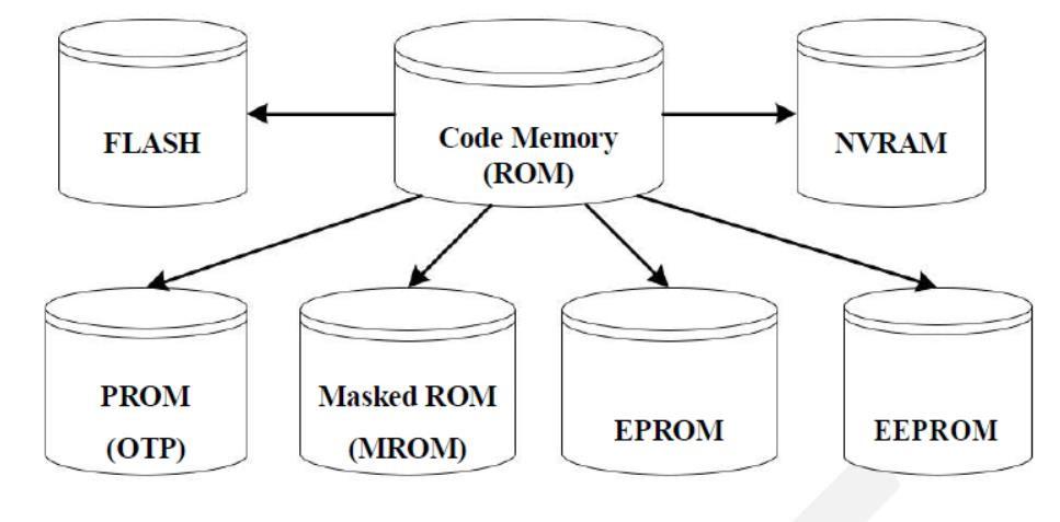
Masked ROM (MROM)
- One-time programmable memory.
- Uses hardwired technology for storing data.
- The device is factory programmed by masking and metallization process according to the data provided by the end user.
- The primary advantage of MROM is low cost for high volume production.
- MROM is the least expensive type of solid-state memory.
- Different mechanisms are used for the masking process of the ROM, like
→ Creation of an enhancement or depletion mode transistor through channel implant
→ By creating the memory cell either using a standard transistor or a high threshold transistor.
→ In the high threshold mode, the supply voltage required to turn ON the transistor is above the normal ROM IC operating voltage.
→ This ensures that the transistor is always off and the memory cell stores always logic 0.
- The limitation with MROM based firmware storage is the inability to modify the device firmware against firmware upgrades.
- The MROM is permanent in bit storage, it is not possible to alter the bit information
Programmable Read Only Memory (PROM) / (OTP)
- It is not pre-programmed by the manufacturer
- The end user is responsible for Programming these devices.
- PROM/OTP has nichrome or polysilicon wires arranged in a matrix; these wires can be functionally viewed as fuses.
- It is programmed by a PROM programmer which selectively burns the fuses according to the bit pattern to be stored.
- Fuses which are not blown/burned represents a logic “1” whereas fuses which are blown/burned represents a logic “0”. The default state is logic “1”.
- OTP is widely used for commercial production of embedded systems whose proto-typed versions are proven and the code is finalized.
- It is a low-cost solution for commercial production.
- OTPs cannot be reprogrammed.
Erasable Programmable Read Only Memory (EPROM):
- Erasable Programmable Read Only (EPROM) memory gives the flexibility to re-program the same chip.
- During development phase, code is subject to continuous changes and using an OTP is not economical.
- EPROM stores the bit information by charging the floating gate of an FET
- Bit information is stored by using an EPROM Programmer, which applies high voltage to charge the floating gate
- EPROM contains a quartz crystal window for erasing the stored information. If the window is exposed to Ultra violet rays for a fixed duration, the entire memory will be erased
- Even though the EPROM chip is flexible in terms of re-programmability, it needs to be taken out of the circuit board and needs to be put in a UV eraser device for 20 to 30 minutes
Electrically Erasable Programmable Read Only Memory (EEPROM):
- Erasable Programmable Read Only (EPROM) memory gives the flexibility to re-program the same chip using electrical signals
- The information contained in the EEPROM memory can be altered by using electrical signals at the register/Byte level
- They can be erased and reprogrammed within the circuit
- These chips include a chip erase mode and in this mode they can be erased in a few milliseconds
- It provides greater flexibility for system design
- The only limitation is their capacity is limited when compared with the standard ROM (A few kilobytes).
Program Storage Memory – FLASH
- FLASH memory is a variation of EEPROM technology.
- FALSH is the latest ROM technology and is the most popular ROM technology used in today’s embedded designs
- It combines the re-programmability of EEPROM and the high capacity of standard ROMs
- FLASH memory is organized as sectors (blocks) or pages
- FLASH memory stores information in an array of floating gate MOSFET transistors
- The erasing of memory can be done at sector level or page level without affecting the other sectors or pages
- Each sector/page should be erased before re-programming
- The typical erasable capacity of FLASH is of the order of a few 1000 cycles.
4.7.2. Read-Write Memory/Random Access Memory (RAM)
- RAM is the data memory or working memory of the controller/processor
- RAM is volatile, meaning when the power is turned off, all the contents are destroyed
- RAM is a direct access memory, meaning we can access the desired memory location directly without the need for traversing through the entire memory locations to reach the desired memory position (i.e. Random Access of memory location)
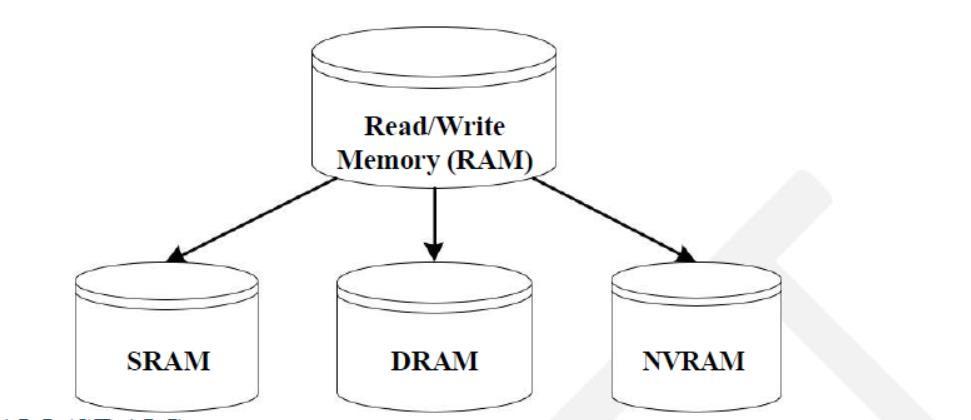
Static RAM (SRAM):
- Static RAM stores data in the form of Voltage.
- They are made up of flip-flops
- In typical implementation, an SRAM cell (bit) is realized using 6 transistors (or 6 MOSFETs).
- Four of the transistors are used for building the latch (flip-flop) part of the memory cell and 2 for controlling the access.
- Static RAM is the fastest form of RAM available
- SRAM is fast in operation due to its resistive networking and switching capabilities
Dynamic RAM (DRAM)
- Dynamic RAM stores data in the form of charge. They are made up of MOS transistor gates
- The advantages of DRAM are its high density and low cost compared to SRAM
- The disadvantage is that since the information is stored as charge it gets leaked off with time and to prevent this, they need to be refreshed periodically
- Special circuits called DRAM controllers are used for the refreshing operation. The refresh operation is done periodically in milliseconds interval
Non-Volatile RAM (NVRAM)
- Random access memory with battery backup
- It contains Static RAM based memory and a minute battery for providing supply to the memory in the absence of external power supply
- The memory and battery are packed together in a single package
- NVRAM is used for the nonvolatile storage of results of operations or for setting up of flags etc
- The life span of NVRAM is expected to be around 10 years
- DS1744 from Maxim/Dallas is an example for 32KB NVRAM
SRAM Cell | DRAM Cell |
Made up of 6 CMOS transistors (MOSFET) | Made up of a MOSFET and a capacitor |
Doesn’t Require refreshing | Requires refreshing |
Low capacity (Less dense) | High Capacity (Highly dense) |
More expensive | Less Expensive |
Fast in operation. Typical access time is 10ns | Slow in operation due to refresh requirements. Typical access time is 60ns. Write operation is faster than read operation. |
Sensors & Actuators
- Embedded system is in constant interaction with the real world
- Controlling/monitoring functions executed by the embedded system is achieved in accordance with the changes happening to the Real World.
- The changes in the system environment or variables are detected by the sensors connected to the input port of the embedded system.
- If the embedded system is designed for any controlling purpose, the system will produce some changes in controlling variable to bring the controlled variable to the desired value.
- It is achieved through an actuator connected to the out port of the embedded system.
Sensor
- A transducer device which converts energy from one form to another for any measurement or control purpose. Sensors acts as input device
- Eg. Hall Effect Sensor which measures the distance between the cushion and magnet in the Smart Running shoes from adidas
- Example: IR, humidity, PIR (passive infra-red), ultrasonic, piezoelectric, smoke sensors
Actuator
- A form of transducer device (mechanical or electrical) which converts signals to corresponding physical action (motion). Actuator acts as an output device
- Eg. Micro motor actuator which adjusts the position of the cushioning element in the Smart Running shoes from adidas
The I/O Subsystem
- The I/O subsystem of the embedded system facilitates the interaction of the embedded system with external world
- The interaction happens through the sensors and actuators connected to the Input and output ports respectively of the embedded system
- The sensors may not be directly interfaced to the Input ports, instead they may be interfaced through signal conditioning and translating systems like ADC, Optocouplers etc
I/O Devices - Light Emitting Diode (LED):
- Light Emitting Diode (LED) is an output device for visual indication in any embedded system
- LED can be used as an indicator for the status of various signals or situations.
- Typical examples are indicating the presence of power conditions like “Device ON‟, “Battery low‟ or “Charging of battery‟ for a battery operated handheld embedded devices
- LED is a p-n junction diode and it contains an anode and a cathode.
- For proper functioning of the LED, the anode of it should be connected to +ve terminal of the supply voltage and cathode to the –ve terminal of supply voltage
- The current flowing through the LED must limited to a value below the maximum current that it can conduct.
- A resister is used in series between the power supply and the resistor to limit the current through the LED
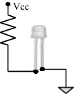

GND
I/O Devices – 7-Segment LED Display
- The 7 – segment LED display is an output device for displaying alpha numeric characters
- It contains 8 light-emitting diode (LED) segments arranged in a special form. Out of the 8 LED segments, 7 are used for displaying alpha numeric characters
- The LED segments are named A to G and the decimal point LED segment is named as DP
- The LED Segments A to G and DP should be lit accordingly to display numbers and characters
- The 7 – segment LED displays are available in two different configurations, namely; Common anode and Common cathode
- In the Common anode configuration, the anodes of the 8 segments are connected commonly whereas in the Common cathode configuration, the 8 LED segments share a common cathode line
- Based on the configuration of the 7 – segment LED unit, the LED segment anode or cathode is connected to the Port of the processor/controller in the order “A‟ segment to the Least significant port Pin and DP segment to the most significant Port Pin.
- The current flow through each of the LED segments should be limited to the maximum value supported by the LED display unit
- The typical value for the current falls within the range of 20mA
- The current through each segment can be limited by connecting a current limiting resistor to the anode or cathode of each segment
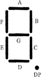
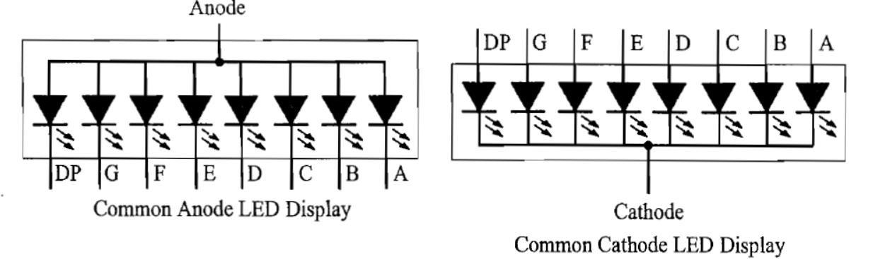
I/O Devices – Stepper Motor:
- Stepper motor is an electro mechanical device which generates discrete displacement (motion) in response to dc electrical signals
- It differs from the normal dc motor in its operation. The dc motor produces continuous rotation on applying dc voltage whereas a stepper motor produces discrete rotation in response to the dc voltage applied to it
- Stepper motors are widely used in industrial embedded applications, consumer electronic products and robotics control systems
- The paper feed mechanism of a printer/fax makes use of stepper motors for its functioning.
- Based on the coil winding arrangements, a two-phase stepper motor is classified into
→ Unipolar
→ Bipolar
- Unipolar: A unipolar stepper motor contains two windings per phase. The direction of rotation (clockwise or anticlockwise) of a stepper motor is controlled by changing the direction of current flow. Current in one direction flows through one coil and in the opposite direction flows through the other coil. It is easy to shift the direction of rotation by just switching the terminals to which the coils are connected
- Bipolar: A bipolar stepper motor contains single winding per phase. For reversing the motor rotation, the current flow through the windings is reversed dynamically. It requires complex circuitry for current flow reversal
The I/O Subsystem – I/O Devices – Push button switch:
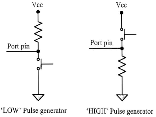
- Push Button switch is an input device.
- Push button switch comes in two configurations, namely “Push to Make‟ and “Push to Break‟
- The switch is normally in the open state and it makes a circuit contact when it is pushed or pressed in the “Push to Make‟ configuration.
- In the “Push to Break‟ configuration, the switch normally in the closed state and it breaks the circuit contact when it is pushed or pressed
- The push button stays in the “closed‟ (For Push to Make type) or “open‟ (For Push to Break type) state as long as it is kept in the pushed state and it breaks/makes the circuit connection when it is released.
- Push button is used for generating a momentary pulse
4.13. Keyboard
- Keyboard is an input device for user interfacing.
- If the number of keys required is very limited, push button switches-can be used and they can be directly interfaced to the port pins for reading.
- However, there may be situations demanding a large number of keys for user input (e.g. PDA device with alpha-numeric keypad for user data entry). In such situations it may not be possible to interface each keys to a port pin due to the limitation in the number of general purpose port pins available for the processor/controller in use and moreover it is wastage of port pins.
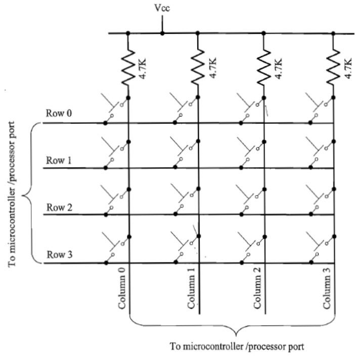
- Matrix keyboard is an optimum solution for handling large key requirements. It greatly reduces the number of interface connections.
- For example, for interfacing 16 keys, in the direct interfacing technique 16 port pins are required, whereas in the matrix keyboard only 8 lines are required.


- The 16 keys are arranged in a 4 column x 4 Row matrix. Figure illustrates the connection of keys in a matrix keyboard.
- In a matrix keyboard, the keys are arranged in matrix fashion (i.e. they are connected in a row and column style). For detecting a key press, the keyboard uses the scanning technique, where each row of the matrix is pulled low and the columns are read.

- After reading the status of each columns corresponding to a row, the row is pulled high and the next row is pulled low and the status of the columns are read. This process is repeated until the scanning for all rows are completed. When a row is pulled low and if a key connected to the row is pressed, reading the column to which the key is connected will give logic 0.

- Since keys are mechanical devices, there is a possibility for de-bounce issues, which may give multiple key press effect for a single key press.

- To prevent this, a proper key de-bouncing technique should be applied. Hardware key de-bouncer circuits and software key de-bounce techniques are the key de- bouncing techniques available.

- The software key de-bouncing technique doesn't require any additional hardware and is easy to implement. In the software de-bouncing technique, on detecting a key-press, the key is read again after a de-bounce delay. If the key press is a genuine one, the state of the key will remain as 'pressed' on the second read also.
- Pull-up resistors are connected to the column lines to limit the current that flows to the Row line on a key press.
I/O Devices – Optocoupler
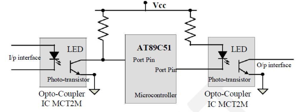
- Optocoupler is a solid-state device to isolate two parts of a circuit.
- Optocoupler combines an LED and a photo-transistor in a single housing (package)
- In electronic circuits, optocoupler is used for suppressing interference in data communication, circuit isolation, High voltage separation, simultaneous separation and intensification signal etc
- Optocouplers can be used in either input circuits or in output circuits
I/O Devices – Relay
- An electro mechanical device which acts as dynamic path selectors for signals and power.
- The “Relay‟ unit contains a relay coil made up of insulated wire on a metal core and a metal armature with one or more contacts.
- “Relay‟ works on electromagnetic principle.
- When a voltage is applied to the relay coil, current flows through the coil, which in turn generates a magnetic field.
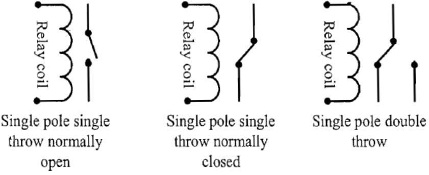
- The magnetic field attracts the armature core and moves the contact point.
- e movement of the contact point changes the power/signal flow path.
- The Relay is normally controlled using a relay driver circuit connected to the port pin of the processor/controller
- A transistor can be used as the relay driver. The transistor can be selected depending on the relay driving current requirements.
Communication Interface
- Communication interface is essential for communicating with various subsystems of the embedded system and with the external world
- The communication interface can be viewed in two different perspectives; namely;
- Device/board level communication interface (Onboard Communication Interface)
- Product level communication interface (External Communication Interface)
Device/board level communication interface (Onboard Communication Interface)
- The communication channel which interconnects the various components within an embedded product is referred as Device/board level communication interface (Onboard Communication Interface)
- Examples: Serial interfaces like I2C, SPI, UART, 1-Wire etc and Parallel bus interface
Product level communication interface (External Communication Interface)
- The “Product level communication interface‟ (External Communication Interface) is responsible for data transfer between the embedded system and other devices or modules. The external communication interface can be either wired media or wireless media and it can be a serial or parallel interface.
- Examples for wireless communication interface: Infrared (IR), Bluetooth (BT), Wireless LAN (Wi-Fi), Radio Frequency waves (RF), GPRS etc.
- Examples for wired interfaces: RS-232C/RS-422/RS 485, USB, Ethernet (TCP-IP), IEEE 1394 port, Parallel port etc.
Device/board level or on-board communication interfaces
- The Communication channel which interconnects the various components within an embedded product is referred as Device/board level communication interface (Onboard Communication Interface)
- These are classified into
→ I2C (Inter Integrated Circuit) Bus
→ SPI (Serial Peripheral Interface) Bus
→ UART (Universal Asynchronous Receiver Transmitter)
→ 1-Wires Interface
→ Parallel Interface
I2C (Inter Integrated Circuit) Bus
Inter Integrated Circuit Bus (I2C - Pronounced “I square C‟) is a synchronous bi-directional half duplex (one-directional communication at a given point of time) two wire serial interface bus. The concept of I2C bus was developed by “Philips Semiconductors‟ in the early 1980’s. The original intention of I2C was to provide an easy way of connection between a microprocessor/microcontroller system and the peripheral chips in Television sets.
The I2C bus is comprised of two bus lines, namely; Serial Clock – SCL and Serial Data – SDA.

I2C Bus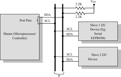
Figure: I2C Bus Interfacing
SCL line is responsible for generating synchronization clock pulses and SDA is responsible for transmitting the serial data across devices. I2C bus is a shared bus system to which many number of I2C devices can be connected. Devices connected to the I2C bus can act as either “Master‟ device or “Slave‟ device.
The “Master‟ device is responsible for controlling the communication by initiating/terminating data transfer, sending data and generating necessary synchronization clock pulses.
Slave devices wait for the commands from the master and respond upon receiving the commands. Master and “Slave‟ devices can act as either transmitter or receiver. Regardless whether a master is acting as transmitter or receiver, the synchronization clock signal is generated by the “Master‟ device only. I2C supports multi masters on the same bus.
The sequence of operation for communicating with an I2C slave device is
- Master device pulls the clock line (SCL) of the bus to “HIGH‟
- Master device pulls the data line (SDA) “LOW‟, when the SCL line is at logic “HIGH‟ (This is the “Start‟ condition for data transfer)
- Master sends the address (7 bit or 10 bit wide) of the “Slave‟ device to which it wants to communicate, over the SDA line.
- Clock pulses are generated at the SCL line for synchronizing the bit reception by the slave device.
- The MSB of the data is always transmitted first.
- The data in the bus is valid during the “HIGH‟ period of the clock signal
- In normal data transfer, the data line only changes state when the clock is low.
- Master waits for the acknowledgement bit from the slave device whose address is sent on the bus along with the Read/Write operation command.
- Slave devices connected to the bus compares the address received with the address assigned to them
- The Slave device with the address requested by the master device responds by sending an acknowledge bit (Bit value =1) over the SDA line
- Upon receiving the acknowledge bit, master sends the 8bit data to the slave device over SDA line, if the requested operation is “Write to device‟.
- If the requested operation is “Read from device‟, the slave device sends data to the master over the SDA line.
- Master waits for the acknowledgement bit from the device upon byte transfer complete for a write operation and sends an acknowledge bit to the slave device for a read operation
- Master terminates the transfer by pulling the SDA line “HIGH‟ when the clock line SCL is at logic “HIGH‟ (Indicating the “STOP‟ condition).
Serial Peripheral Interface (SPI) Bus
- The Serial Peripheral Interface Bus (SPI) is a synchronous bi-directional full duplex four wire serial interface bus. The concept of SPI is introduced by Motorola. SPI is a single master multi-slave system.
- It is possible to have a system where more than one SPI device can be master, provided the condition only one master device is active at any given point of time, is satisfied.
- SPI is used to send data between Microcontrollers and small peripherals such as shift registers, sensors, and SD cards.
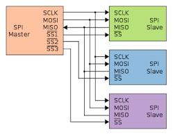
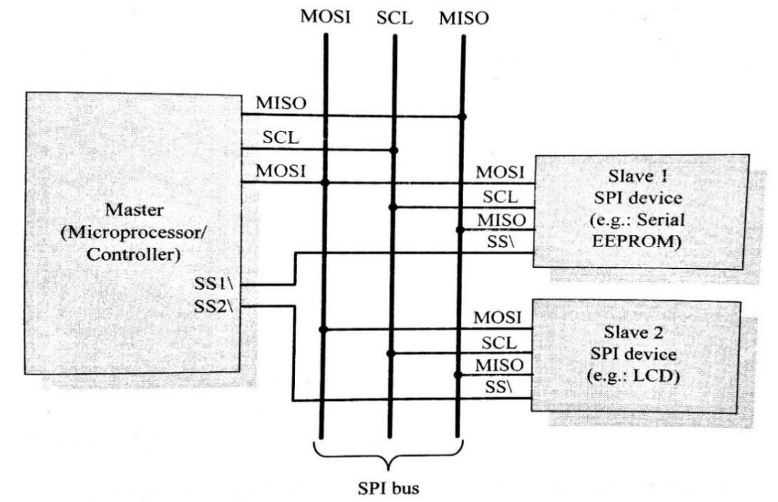
Figure: SPI bus Interfacing
SPI requires four signal lines for communication. They are:
Master Out Slave In (MOSI): Signal line carrying the data from master to slave device. It is also known as Slave Input/Slave Data In (SI/SDI)
Master In Slave Out (MISO): Signal line carrying the data from slave to master device. It is also known as Slave Output (SO/SDO)
Serial Clock (SCLK): Signal line carrying the clock signals
Slave Select (SS): Signal line for slave device select. It is an active low signal. The master device is responsible for generating the clock signal.
Master device selects the required slave device by asserting the corresponding slave devices slave select signal “LOW‟.
- The data out line (MISO) of all the slave devices when not selected floats at high impedance state
- The serial data transmission through SPI Bus is fully configurable.
- SPI devices contain certain set of registers for holding these configurations.
- The Serial Peripheral Control Register holds the various configuration parameters like master/slave selection for the device, baudrate selection for communication, clock signal control etc.
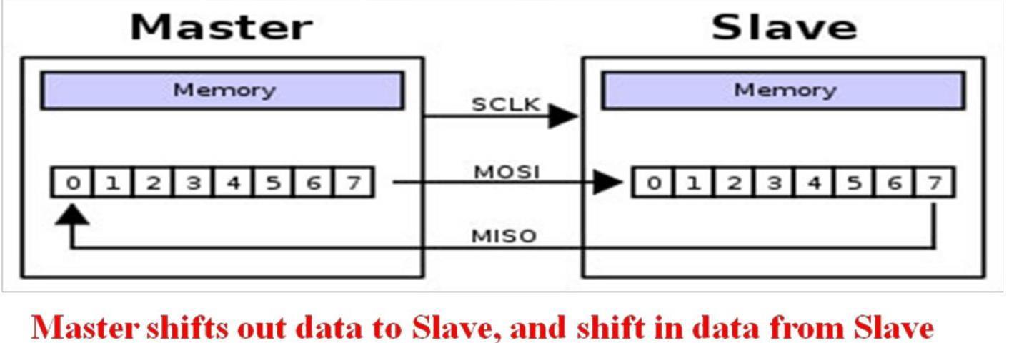
- The status register holds the status of various conditions for transmission and reception. SPI works on the principle of „Shift Register‟.
- The master and slave devices contain a special shift register for the data to transmit or receive.
- The size of the shift register is device dependent. Normally it is a multiple of 8.
- During transmission from the master to slave, the data in the master’s shift register is shifted out to the MOSI pin and it enters the shift register of the slave device through the MOSI pin of the slave device.
- At the same time the shifted out data bit from the slave device’s shift register enters the shift register of the master device through MISO pin
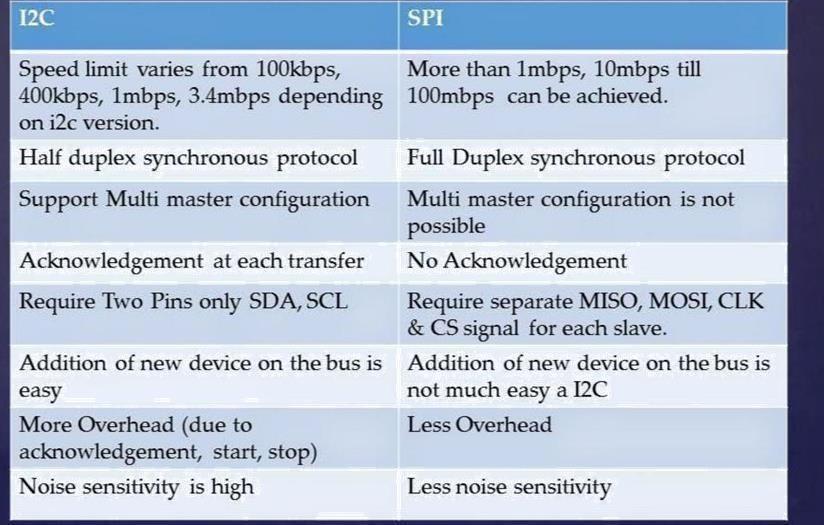
I2C V/S SPI:
Universal Asynchronous Receiver Transmitter (UART)
- Universal Asynchronous Receiver Transmitter (UART) based data transmission is an asynchronous form of serial data transmission.
- UART based serial data transmission doesn’t require a clock signal to synchronize the transmitting end and receiving end for transmission. Instead it relies upon the pre-defined agreement between the transmitting device and receiving device.
- The serial communication settings (Baud rate, number of bits per byte. parity, number of start bits and stop bit and flow control) for both transmitter and receiver should be set as identical. The start and stop of communication is indicated through inserting special bits in the data stream. While sending a byte of data, a start bit is added first and a stop bit is added at the end of the bit stream.
- The least significant bit of the data byte follows the ‘start’ bit.
- The ‘start’ bit informs the receiver that a data byte is about to arrive.
- The receiver device starts polling its received line’ as per the baud rate settings.
- If the baud rate is ‘x’ bits per second, the time slot available for one bit is l /x seconds. The receiver unit polls the receiver line at exactly half of the time slot available for the bit.
- If parity is enabled for communication, the UART of the transmitting device adds a parity bit (bit value is l for odd number of ls in the transmitted bit stream and 0 for even number of is the UART of the receiving device calculates the parity of the bits received and compares it with the received parity bit for error checking.
- The UART of the receiving device discards the ‘Start’, ‘Stop’ and ‘Parity' bit from the received bit stream and converts the received serial bit data to a word (In the case of 8 bits/byte, the byte is formed with the received 8 bits with the first received bit as the LSB and last received data bit as MSB).
- For proper communication, the ‘Transmit line’ of the sending device should be connected to the ‘Receive line’ of the receiving device. Figure illustrates the same.
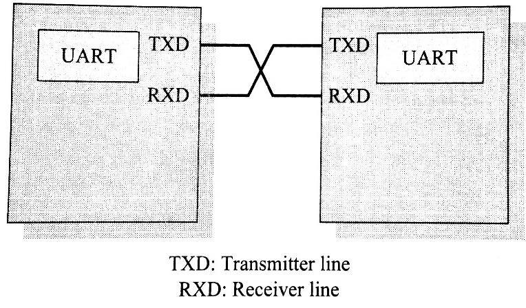
- In addition to the serial data transmission function, UART provides hardware handshake receiver support for controlling the serial data now. UART chips are available from
different semiconductor manufacturers. National Semiconductor’s 8250 UART chip is considered as the standard setting UART. It was used in the original IBM PC.
1-wire interface (protocol)
- 1-wire interface is an asynchronous half-duplex communication protocol developed by Maxim Dallas Semiconductor. It is also known as Dallas 1-Wire® protocol. It makes use of only a single signal line (wire) called DQ for communication and follows the master- slave communication model.
- One of the key feature of l-wire bus is that it allows power to be sent along the signal wire as well.
- The 12C slave devices incorporate internal capacitor (typically of the order of 800 pF) to power the device from the signal line.
- The l-wire interface supports a Single master and one or more slave devices on the bus. The bus interface diagram shown in Figure illustrates the connection of master and slave devices on the l-wire bus.
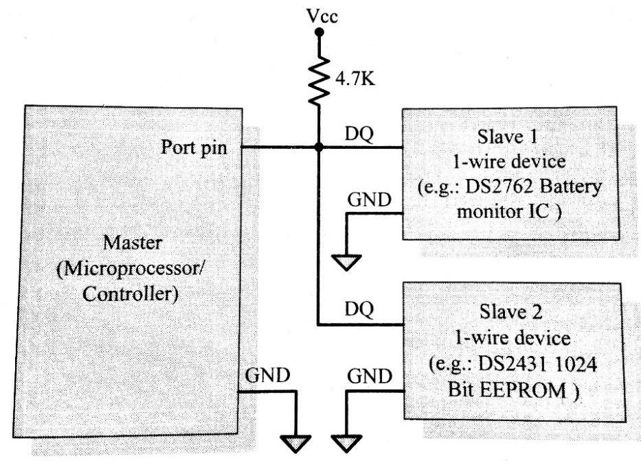
- Every 1-wire device contains a globally unique 64bit identification number stored within it. The unique identification number can be used for addressing individual devices present on the bus in case there are multiple slave devices connected to the 1-wire bus.
- The identifier has three parts: an 8bit family code, a 48bit serial number and an 8-bit CRC computed from the first 56 bits.
- The sequence of operation for communicating with a 1-wire slave device is listed below:
- The master device sends a ‘Reset’ pulse on the l-wire bus.
- The slave device(s) present on the bus respond with a ‘Presence’ pulse.
- The master device sends a ROM command (Net Address Command followed by the 64bit address of the device). This addresses the slave device(s) to which it wants to initiate a communication.
- The master device sends a read/write function command to read/write the internal memory or register of the slave device.
- The master initiates a Read data/Write data from the device or to the device
- All communication over the l-wire bus is master initiated. The communication over the l- wire bus divided into timeslots of 60 microseconds. The ‘Reset’ pulse occupies 8 time slots.
- For starting a communication, the master asserts the reset pulse by pulling the 1-wire bus ‘LOW’ for at least 8 time slots ‘slave’ device is present on the bus and is ready for communication it should respond to the master with a ‘Presence’ pulse, within 60us of the release of the ‘Reset’ pulse by the master.
- The slave device(s) responds with a ‘Presence’ pulse by pulling the l-wire bus ‘LOW’ for a minimum of 1 time slot (60 us).
- For writing a bit value of 1 on the l-wire bus, the bus master pulls the bus for l to l5µs and then releases the bus for the rest of the time slot. A bit value of ‘0’ is written on the bus by master pulling the bus for a minimum of 1 time slot (60µs) and a maximum of 2 time slots (120µs). To Read a bit from the slave device, the master pulls the bus ‘LOW’ for l to 15us. If the slave wants to send a bit value ‘1’ in response to the read request from the master, it simply releases the bus for the rest of the time slot. If the slave wants to send a bit value ‘0’, it pulls the bus ‘LOW’ for the rest of the time slot.
Parallel interface
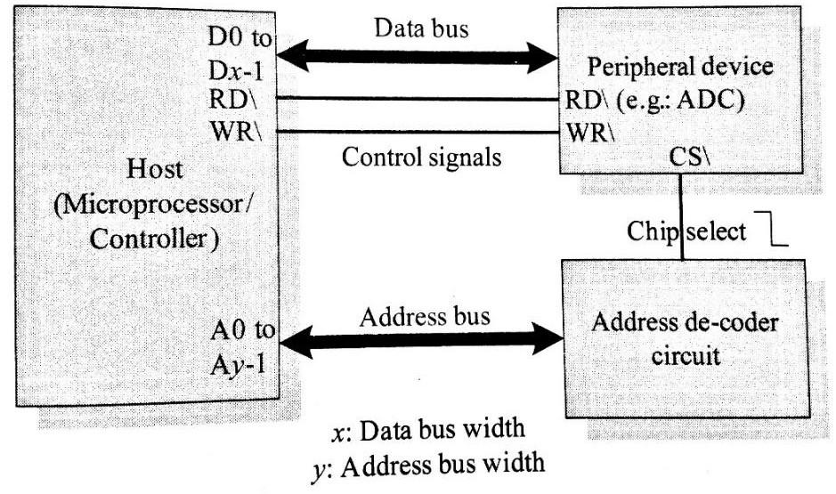
- The on-board parallel interface is normal used for communicating with peripheral devices which are memory mapped to the host of the system.
- The host processor/controller of the embedded system contains a parallel bus and the device which supports parallel bus can directly connect to this bus system.
- The communication through the parallel bus is controlled by the control signal interface between the device and the host.
- The ‘Control Signals’ for communication includes ‘Read/ Write’ signal and device select signal. The device normally contains a device select line and the device becomes active only when this line is asserted by the host processor.
- The direction of data transfer (Host to Device or Device to Host) can be controlled through the control signal lines for ‘Read’ and ‘Write’. Only the host processor has control over the ‘Read’ and ‘Write’ control signals.
- The device is normally memory mapped to the host processor and a range of address is assigned to it. An address decoder circuit is used for generating the chip select signal for the device.
- When the address selected by the processor is within the range assigned for the device, the decoder circuit activates the chip select line and thereby the device becomes active.
- The processor then can read or write from or to the device by asserting the corresponding control line (RD and WR respectively). Strict timing characteristics are followed for parallel communication.
- parallel communication is host processor initiated.
- If a device wants to initiate the communication, it can inform the same to the processor through interrupts. For this, the interrupt line of the device is connected to the interrupt line of the processor and the core, responding interrupt is enabled in the host processor. The width of the parallel interbank is determined by the data bus width of the host processor. It can be 4bit, 8bit, 16bit, 32bit or 64bit etc. The bus width supported by the device should be same as that of the host processor.
- The bus interface diagram shown in Figure illustrates the interfacing of devices through parallel interface.
Product level communication interface (External Communication Interface)
The Product level communication interface (External Communication Interface) is responsible for data transfer between the embedded system and other devices or modules
It is classified into two types
→ Wired communication interface
→ Wireless communication interface:
Wired communication interface
Wired communication interface is an interface used to transfer information over a wired network. It is classified into following types.
→ RS-232C/RS-422/RS 485
→ USB
RS-232C:
- RS-232 C (Recommended Standard number 232, revision C from the Electronic Industry Association) is a legacy, full duplex, wired, asynchronous serial communication interface
- RS-232 extends the UART communication signals for external data communication.
- UART uses the standard TTL/CMOS logic (Logic “High‟ corresponds to bit value 1 and Logic “LOW‟ corresponds to bit value 0) for bit transmission whereas RS232 use the EIA standard for bit transmission.
- As per EIA standard, a logic “0‟ is represented with voltage between +3 and +25V and a logic “1‟ is represented with voltage between -3 and -25V.
- In EIA standard, logic “0‟ is known as “Space‟ and logic “1‟ as “Mark‟.
- The RS232 interface define various handshaking and control signals for communication apart from the “Transmit‟ and “Receive‟ signal lines for data communication
- RS-232 supports two different types of connectors, namely; DB-9: 9-Pin connector and DB-25: 25-Pin connector.

- RS-232 is a point-to-point communication interface and the devices involved in RS-232 communication are called “Data Terminal Equipment (DTE)‟ and “Data Communication Equipment (DCE)‟.
- If no data flow control is required, only TXD and RXD signal lines and ground line (GND) are required for data transmission and reception.
- The RXD pin of DCE should be connected to the TXD pin of DTE and vice versa for proper data transmission.
- If hardware data flow control is required for serial transmission, various control signal lines of the RS-232 connection are used appropriately.
- The control signals are implemented mainly for modem communication and some of them may be irrelevant for other type of devices.
- The Request to Send (RTS) and Clear To Send (CTS) signals co-ordinate the communication between DTE and DCE.
- Whenever the DTE has a data to send, it activates the RTS line and if the DCE is ready to accept the data, it activates the CTS line.
- The Data Terminal Ready (DTR) signal is activated by DTE when it is ready to accept data.
- The Data Set Ready (DSR) is activated by DCE when it is ready for establishing a communication link.
- DTR should be in the activated state before the activation of DSR.
- The Data Carrier Detect (DCD) is used by the DCE to indicate the DTE that a good signal is being received.
- Ring Indicator (RI) is a modem specific signal line for indicating an incoming call on the telephone line.
- As per the EIA standard RS-232 C supports baudrates up to 20Kbps (Upper limit 19.2Kbps).
- The commonly used baudrates by devices are 300bps, 1200bps, 2400bps, 9600bps,
11.52Kbps and 19.2Kbps.
- The maximum operating distance supported in RS-232 communication is 50 feet at the highest supported baudrate.
- Embedded devices contain a UART for serial communication and they generate signal levels conforming to TTL/CMOS logic.
- A level translator IC like MAX 232 from Maxim Dallas semiconductor is used for converting the signal lines from the UART to RS-232 signal lines for communication.
- On the receiving side the received data is converted back to digital logic level by a converter IC.
USB (UNIVERSAL SERIAL BUS):
- Universal Serial Bus (USB) is a wired high speed serial bus for data communication.
- The first version of USB (USB1.0) was released in 1995 and was created by the USB core group members consisting of Intel, Microsoft, IBM, Compaq, Digital and Northern Telecom.
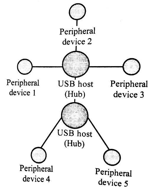
- The USB communication system follows a star topology with a USB host at the center and one or more USB peripheral devices/USB hosts connected to it.
- A USB host can support connections up to 127, including slave peripheral devices and other USB hosts. Figure illustrates the star topology for USB device connection.
- USB transmits data in packet format. Each data packet has a standard format. The USB communication is a host initiated one.
- The USB host contains a host controller which is responsible for controlling the data communication, including establishing connectivity with USB slave devices, packetizing and formatting the data.
- There are different standards for implementing the USB Host Control interface; namely Open Host Control Interface (OHCI) and Universal Host Control Interface (UHCI).
- USB uses differential signals for data transmission. It improves the noise immunity.
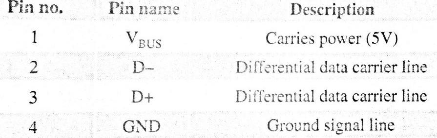
- USB interface has the ability to supply power to the connecting devices. Two connection lines (Ground and Power) of the USB interface are dedicated for carrying power. It can supply power up to 500 mA at 5 V. It is sufficient to operate low power devices. Mini and Micro USB connectors are available for small form factor devices like portable media players.
- The pin details for connectors are listed below:
- Each USB device contains a Product ID (PID) and a Vendor ID (VID). The PID and VID are embedded into the USB chip by the USB device manufacturer. The VID for a device is supplied by the USB standards forum. PID and VID are essential for loading the drivers corresponding to a USB device for communication.
- USB supports four different types of data transfers, namely; Control, Bulk, Isochronous and Interrupt.
- Control transfer is used by USB system software to query, configure and issue commands to the USB device.
- Bulk transfer is used for sending a block of data to a device. Bulk transfer supports error checking and correction. Transferring data to a printer is an example for bulk transfer.
- Isochronous data transfer is used for real-time data communication. In Isochronous transfer, data is transmitted as streams in real-time. Isochronous transfer doesn’t support error checking and re-transmission of data in case of any transmission loss. All streaming devices like audio devices and medical equipment for data collection make use of the isochronous transfer.
- Interrupt transfer is used for transferring small amount of data. Interrupt transfer mechanism makes use of polling technique to see whether the USB device has any data to send. The frequency of polling is determined by the USB device and it varies from 1 to 255 milliseconds. Devices like Mouse and Keyboard, which transmits fewer amounts of data, uses interrupt transfer.
IEEE 1394 (Fire wire):
- IEEE 1394 is a wired, isochronous high speed serial communication bus. It is also known as High Performance Serial Bus (HPSB).
- The research on 1394 was started by Apple Inc. in 1985 and the standard for this was coined by IEEE. The implementation of it is available from various players with different names. Apple Inc.’s (www.apple.com) implementation of 1394 protocol is popularly known as Fir- mire.
- LLINK is the 1394 implementation from Sony Corporation (www.sony.netl and Lynx is the implementation from Texas Instruments www.ti.com).
- 1394 supports peer-to-peer connection and point-to-multipoint communication allowing 63 devices to be connected on the bus in a nee topology.
- 1394 is a wired serial interface and it can support a cable length of up to 15 feet for interconnection.
- The 1394 standard has evolved a lot from the first version IEEE 1394-1995 released in 1995 to the recent version IEEE 1394-2008 released in June 2008. The 1394 standard supports a data rate of 400 to 3200Mbits/second.
- The IEEE 1394 uses differential data transfer (The information is sent using differential signals through a pair of twisted cables. It increases the noise immunity) and the interface cable supports 3 types of connectors, namely; 4-pin connector, 6-pin connector (alpha connector) and 9 pin connectors (beta connector).
- The 6 and 9 pin connectors carry power also to support external devices (In case an embedded device is connected to a PC through an IEEE 1394 cable with 6 or 9 pin connector interface, it can operate from the power available through the connector.) It can supply unregulated power in the range of 24 to 30V.
(The Apple implementation is for battery operated devices and it can supply a voltage in the range 9 to 12V.)
- The table given below illustrates the pin details for 4, 6 and 9 pin connectors.
Pin Name | Pin No: (4 Pin Connector) | Pin No: (6 Pin Connector) | Pin No: (9 Pin Connector) | Description |
Power |
| 1 | 8 | Unregulated DC supply. 24 to 30V |
Signal Ground |
| 2 | 6 | Ground connection |
TPB- | 1 | 3 | 1 | Differential Signal line for Signal Line B |
TPB+ | 2 | 4 | 2 | Differential Signal line for Signal Line B |
TPA- | 3 | 5 | 3 | Differential Signal line for Signal Line A |
TPA+ | 4 | 6 | 4 | Differential Signal line for Signal Line A |
TPA(S) |
|
| 5 | Shield for the differential signal line A. Normally grounded |
TPB(S) |
|
| 9 | Shield for the differential signal line B. Normally grounded |
NC |
|
| 7 | No connection |
- There are two differential data transfer lines A and B per connector. In a 1394 cable, normally the differential lines of A are connected to B (TPA+ to TPB+ and TPA-to TPB~) and vice versa.
- 1394 is a popular communication interface for connecting embedded devices like Digital Camera, Camcorder, and Scanners to desktop computers for data transfer and storage.
- Unlike USB interface (Except USB OTG), IEEE 1394 doesn‘t require a host for communicating between devices.
- For example, you can directly connect a scanner with a printer for printing. The data rate supported by 1394 is far higher than the one supported by USB2.0 interface.
- The 1394 hardware implementation is much costlier than USB implementation.
Wireless communication interface
Wireless communication interface is an interface used to transmission of information over a distance without help of wires, cables or any other forms of electrical conductors.
They are basically classified into following types
- Infrared
- Bluetooth
- Wi-Fi
- Zigbee
GPRS
INFRARED:
- Infrared is a certain region in the light spectrum
- Ranges from .7μ to 1000μ or .1mm
- Broken into near, mid, and far infrared
- One step up on the light spectrum from visible light
- Measure of heat
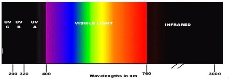
Most of the thermal radiation emitted by objects near room temperature is infrared. Infrared radiation is used in industrial, scientific, and medical applications. Night-vision devices using active near-infrared illumination allow people or animals to be observed without the observer being detected.
IR transmission:
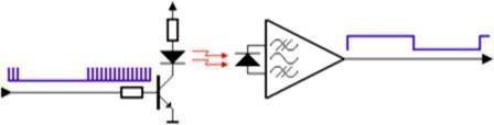
The transmitter of an IR LED inside its circuit, which emits infrared light for every electric pulse given to it. This pulse is generated as a button on the remote is pressed, thus completing the circuit, providing bias to the LED.
The LED on being biased emits light of the wavelength of 940nm as a series of pulses, corresponding to the button pressed. However, since along with the IR LED many other sources of infrared light such as us human beings, light bulbs, sun, etc, the transmitted information can be interfered. A solution to this problem is by modulation. The transmitted signal is modulated using a carrier frequency of 38 KHz (or any other frequency between 36 to 46 KHz). The IR LED is made to oscillate at this frequency for the time duration of the pulse. The information or the light signals are pulse width modulated and are contained in the 38 KHz frequency.
IR supports data rates ranging from 9600bits/second to 16Mbps Serial infrared: 9600bps to 115.2 kbps
Medium infrared: 0.576Mbps to 1.152 Mbps Fast infrared: 4Mbps
Bluetooth:
- Bluetooth is a wireless technology standard for short distances (using short-wavelength UHF band from 2.4 to 2.485 GHz) for exchanging data over radio waves in the ISM and mobile devices, and building personal area networks (PANs).
- Invented by telecom vendor Ericsson in 1994, it was originally conceived as a wireless alternative to RS- 232 data cables.
- Bluetooth uses a radio technology called frequency- hopping spread spectrum. Bluetooth divides transmitted data into packets, and transmits each packet on one of 79 designated Bluetooth channels. Each channel has a bandwidth of 1 MHz. It usually performs 800 hops per second, with Adaptive Frequency-Hopping (AFH) enabled
- Originally, Gaussian frequency-shift keying (GFSK) modulation was the only modulation scheme available. Since the introduction of Bluetooth 2.0+EDR, π/4-DQPSK (Differential Quadrature Phase Shift Keying) and 8DPSK modulation may also be used between compatible devices.
- Bluetooth is a packet-based protocol with a master- slave structure. One master may communicate with up to seven slaves in a piconet. All devices share the master's clock. Packet exchange is based on the basic clock, defined by the master, which ticks at 312.5 μs intervals.
- A master BR/EDR Bluetooth device can communicate with a maximum of seven devices in a piconet (an ad-hoc computer network using Bluetooth technology), though not all devices reach this maximum.
- The devices can switch roles, by agreement, and the slave can become the master (for example, a headset initiating a connection to a phone necessarily begins as master—as initiator of the connection—but may subsequently operate as slave).
Wi-Fi:
- Wi-Fi is the name of a popular wireless networking technology that uses radio waves to provide wireless high-speed Internet and network connections
- Wi-Fi follows the IEEE 802.11 standard
- Wi-Fi is intended for network communication and it supports Internet Protocol (IP) based communication
- Wi-Fi based communications require an intermediate agent called Wi-Fi router/Wireless Access point to manage the communications.
- The Wi-Fi router is responsible for restricting the access to a network, assigning IP address to devices on the network, routing data packets to the intended devices on the network.
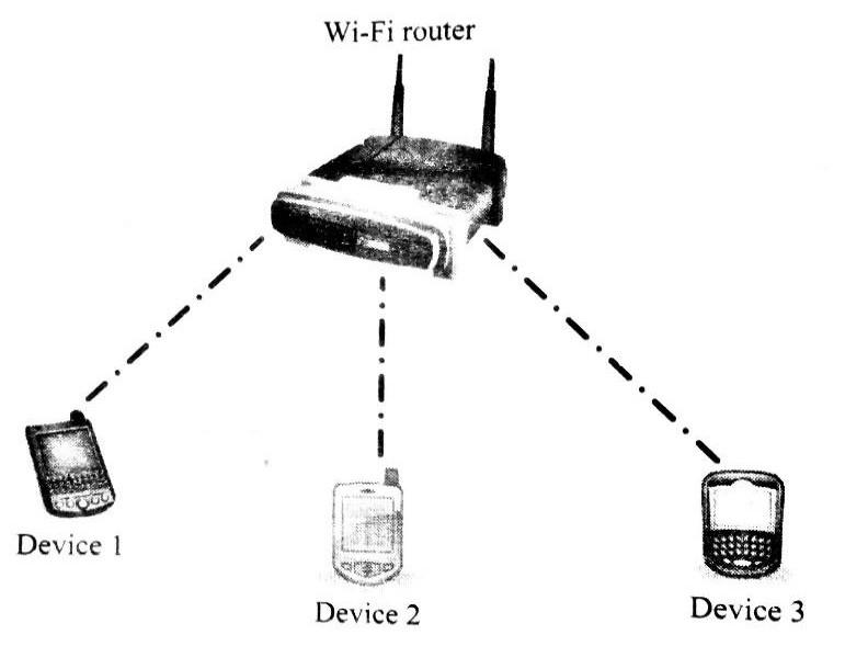
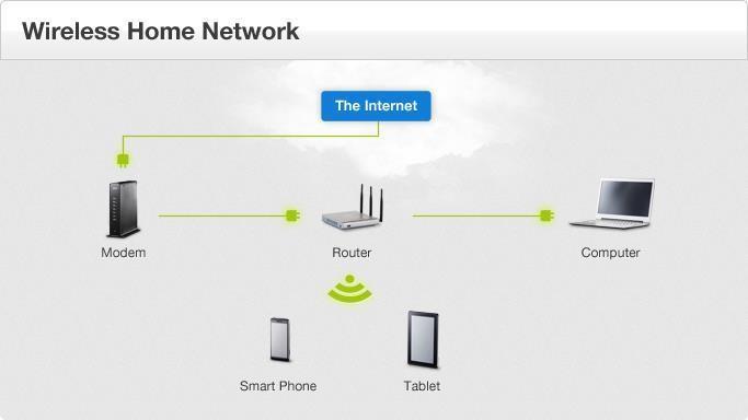
- Wi-Fi enabled devices contain a wireless adaptor for transmitting and receiving data in the form of radio signals through an antenna.
- Wi-Fi operates at 2.4GHZ or 5GHZ of radio spectrum and they co-exist with other ISM band devices like Bluetooth.
- A Wi-Fi network is identified with a Service Set Identifier (SSID). A Wi-Fi device can connect to a network by selecting the SSID of the network and by providing the credentials if the network is security enabled
- Wi-Fi networks implements different security mechanisms for authentication and data transfer.
- Wireless Equivalency Protocol (WEP), Wireless Protected Access (WPA) etc are some of the security mechanisms supported by Wi-Fi networks in data communication.
ZIGBEE:
- Zigbee is an IEEE 802.15.4-based specification for a suite of high- level communication protocols used to create personal area networks with small, low-power digital radios, such as for home automation, medical device data collection, and other low-power low- bandwidth needs, designed for small scale projects which need wireless connection. Hence, ZigBee is a low-power, low data rate, and close proximity (i.e., personal area) wireless ad hoc network.
- The technology defined by the ZigBee specification is intended to be simpler and less expensive than other wireless personal area networks (WPANs), such as Bluetooth or Wi- Fi .
- Applications include wireless light switches, electrical meters with in-home-displays, traffic management systems, and other consumer and industrial equipment that require short-range low- rate wireless data transfer.
- Its low power consumption limits transmission distances to 10– 100 meters line-of-sight, depending on power output and environmental characteristics.
- Zigbee devices can transmit data over long distances by passing data through a mesh network of intermediate devices to reach more distant ones.
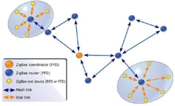
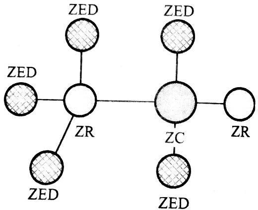
- Zigbee Coordinator: The ZigBee coordinator acts as the root of the ZigBee network. The ZC is responsible for initiating the Zigbee network and it has the capability to store information about the network.
- Zigbee Router: Responsible for passing information from device to another device or to another ZR.
- Zigbee end device: End device containing ZigBee functionality for data communication. It can talk only with a ZR or ZC and doesn’t have the capability to act as a mediator for transferring data from one device to another.
- Zigbee supports an operating distance of up to 100 metres at a data rate of 20 to 250 Kbps
General Packet Radio Service (GPRS)
- General Packet Radio Service (GPRS) is a packet oriented mobile data service on the 2G and 3G cellular communication system's global system for mobile communications (GSM).
- GPRS was originally standardized by European Telecommunications Standards Institute (ETSI) GPRS usage is typically charged based on volume of data transferred, contrasting with circuit switched data, which is usually billed per minute of connection time. Sometimes billing time is broken down to every third of a minute. Usage above the bundle cap is charged per megabyte, speed limited, or disallowed.
Services offered:
- GPRS extends the GSM Packet circuit switched data capabilities and makes the following services possible:
- SMS messaging and broadcasting
- "Always on" internet access
- Multimedia messaging service (MMS)
- Push-to-talk over cellular (PoC)
- Instant messaging and presence-wireless village Internet applications for smart devices through wireless application protocol (WAP).
- Point-to-point (P2P) service: inter-networking with the Internet (IP).
- Point-to-multipoint (P2M) service]: point-to- multipoint multicast and point-to- multipoint group calls.
Embedded Firmware
The control algorithm (Program instructions) and or the configuration settings that an embedded system developer dumps into the code (Program) memory of the embedded system The embedded firmware can be developed in various methods like
- Write the program in high level languages like Embedded C/C++ using an Integrated Development Environment (The IDE will contain an editor, compiler, linker, debugger, simulator ) etc. IDEs (Keil) are different for different family of processors/controllers.
- Write the program in Assembly Language using the Instructions Supported by your application’s target processor/controller
Other System Components –
- Reset Circuit
- The Reset circuit is essential to ensure that the device is not operating at a voltage level where the device is not guaranteed to operate, during system power ON.
- The Reset signal brings the internal registers and the different hardware systems of the processor/controller to a known state and starts the firmware execution from the reset vector (Normally from vector address 0x0000 for conventional processors/controllers.
- The reset vector can be relocated to an address for processors/controllers supporting bootloader.
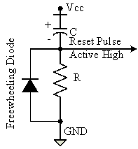
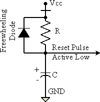
- The reset signal can be either active high (The processor undergoes reset when the reset pin of the processor is at logic high) or active low (The processor undergoes reset when the reset pin of the processor is at logic low).
Brown-out Protection Circuit
- Brown-out protection circuit prevents the processor/controller from unexpected program execution behavior when the supply voltage to the processor/controller falls below a specified voltage.
- The processor behavior may not be predictable if the supply voltage falls below the recommended operating voltage. It may lead to situations like data corruption.
- A brown-out protection circuit holds the processor/controller in reset state, when the operating voltage falls below the threshold, until it rises above the threshold voltage. Certain processors/controllers support built in brown-out protection circuit which monitors the supply voltage internally.
D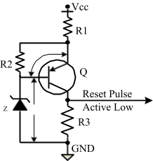


- If the processor/controller doesn’t integrate a built-in brown-out protection circuit, the same can be implemented using external passive circuits or supervisor ICs
Oscillator Unit
- A microprocessor/microcontroller is a digital device made up of digital combinational and sequential circuits.
- The instruction execution of a microprocessor/controller occurs in sync with a clock signal. The oscillator unit of the embedded system is responsible for generating the precise clock for the processor.
- Quartz crystal Oscillators are example for clock pulse generating devices
Real Time Clock (RTC)
- It is a system component responsible for keeping track of time.
- RTC holds information like current time (In hour, minutes and seconds) in 12 hour /24 hour format, date, month, year, day of the week etc and supplies timing reference to the system.
- RTC is intended to function even in the absence of power.
- RTCs are available in the form of Integrated Circuits from different semiconductor manufacturers like Maxim/Dallas, ST Microelectronics etc
- The RTC chip contains a microchip for holding the time and date related information and backup battery cell for functioning in the absence of power, in a single IC package.
- The RTC chip is interfaced to the processor or controller of the embedded system. For Operating System based embedded devices, a timing reference is essential for synchronizing the operations of the OS kernel.
- The RTC can interrupt the OS kernel by asserting the interrupt line of the processor/controller to which the RTC interrupt line is connected. The OS kernel identifies the interrupt in terms of the Interrupt Request (IRQ) number generated by an interrupt controller.
- One IRQ can be assigned to the RTC interrupt and the kernel can perform necessary operations like system date time updation, managing software timers etc when an RTC timer tick interrupt occurs
Watch Dog Timer
- The watchdog timer is a timing device that resets the system after a predefined timeout.
- It is activated within the first few clock cycles after power-up.
- It helps in rescuing the system if a fault develops and program gets stuck.
- On restart, the system functions normally. The watchdog timer reset is a required feature in control applications.
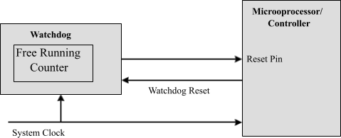
- Depending on the internal implementation, the watchdog timer increments or decrements a free running counter with each clock pulse and generates a reset signal to reset the processor if the count reaches zero for a down counting watchdog, or the highest count value for an up-counting watchdog.
- If the firmware execution doesn’t complete due to malfunctioning, within the time required by the watchdog to reach the maximum count, the counter will generate a reset pulse and this will reset the processor.
- If the firmware execution completes before the expiration of the watchdog timer the WDT can be stopped from action
- Most of the processors implement watchdog as a built-in component and provides status register to control the watchdog timer (like enabling and disabling watchdog functioning) and watchdog timer register for writing the count value.
- If the processor/controller doesn’t contain a built-in watchdog timer, the same can be implemented using an external watchdog timer IC circuit.